Magic smoke

Lez2000

Registered
2 Oct 2019
129
6
73
Sutton Coldfield, West Midlands
Best answers
0
Country flag
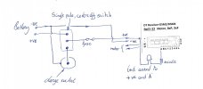
Hello all, I was going to ask if any of you could tell me why I had a tiny wisp of smoke when attempting to charge my NiMh batteries in situ but looking at my wiring diagram I think I can see why.
Please correct me if I'm wrong but I think the battery should have gone to the centre contact and the output to the receiver to the top contact. The way I've wired it it would appear the charging voltage goes straight to the receiver:mad: with the inevitable result.

Next question; does anyone repair these receivers? (RX65-22).

Thanks,
Les, feeling rather stupid at the moment.
running charging circuit.jpg
 
Last edited:

PhilP

G Scale, 7/8th's, Electronics
5 Jun 2013
33,559
3,521
Nottingham
Best answers
0
Country flag
Hi Les,

Both diagrams appear to be the same?

If you are *very* lucky, you will have blown the regulator chip which supplies the processors with 3.3V.

First thing, is to examine your receiver for obviously blown components.
Next, would be to see if the processors still work. - If they do, then the regulator can be swapped for something beefier.

If you want to contact me directly, I can explain how you can test the Rx. - It is not something I would want everybody to try, so I am loath to put the information online.

PhilP
Phil@rctrains.co.uk
 

Lez2000

Registered
2 Oct 2019
129
6
73
Sutton Coldfield, West Midlands
Best answers
0
Country flag
Hi Les,

Both diagrams appear to be the same?

If you are *very* lucky, you will have blown the regulator chip which supplies the processors with 3.3V.

First thing, is to examine your receiver for obviously blown components.
Next, would be to see if the processors still work. - If they do, then the regulator can be swapped for something beefier.

If you want to contact me directly, I can explain how you can test the Rx. - It is not something I would want everybody to try, so I am loath to put the information online.

PhilP
Phil@rctrains.co.uk
Hi Phil,
thanks for your quick reply. I didn't intend to post two diagrams so I've removed one.
I can't see any obvious signs of damage.

I'll pm for more information.

Regards,
Les.
 

Rhinochugger

Retired Oik
27 Oct 2009
36,707
4,240
North West Norfolk
Best answers
0
Country flag
Hello all, I was going to ask if any of you could tell me why I had a tiny wisp of smoke when attempting to charge my NiMh batteries in situ but looking at my wiring diagram I think I can see why.
Please correct me if I'm wrong but I think the battery should have gone to the centre contact and the output to the receiver to the top contact. The way I've wired it it would appear the charging voltage goes straight to the receiver:mad: with the inevitable result.

Next question; does anyone repair these receivers? (RX65-22).

Thanks,
Les, feeling rather stupid at the moment.

View attachment 285271
Yes, for a Double throw switch, the power input should go to the centre, and the two outputs are switched on or off as the switch is operated.

It's also worth noting that the switch operates opposite to the direction of the lever so, as in your diagram, if you point the switch up, the charging socket will be live (after you've re-wired the switch that is) and when you point it down the loco will be live.

Magic smoke is quite rare - that's why it's so expensive :oops::oops::oops:
 

Lez2000

Registered
2 Oct 2019
129
6
73
Sutton Coldfield, West Midlands
Best answers
0
Country flag
Yes, for a Double throw switch, the power input should go to the centre, and the two outputs are switched on or off as the switch is operated.

It's also worth noting that the switch operates opposite to the direction of the lever so, as in your diagram, if you point the switch up, the charging socket will be live (after you've re-wired the switch that is) and when you point it down the loco will be live.

Magic smoke is quite rare - that's why it's so expensive :oops::oops::oops:
Yes, it's obvious now where the connections should be. The annoying thing is, I've been working with wiring diagrams for a considerable part of my working life! Just shows what a moments lapse of concentration does.

Regards,
Les.
 

Rhinochugger

Retired Oik
27 Oct 2009
36,707
4,240
North West Norfolk
Best answers
0
Country flag
Yes, it's obvious now where the connections should be. The annoying thing is, I've been working with wiring diagrams for a considerable part of my working life! Just shows what a moments lapse of concentration does.

Regards,
Les.
We've all done it :rock::rock::rock::rock::rock:
 

PhilP

G Scale, 7/8th's, Electronics
5 Jun 2013
33,559
3,521
Nottingham
Best answers
0
Country flag
That's too old! :mm::nerd:

Only good for DC, And up-to 27MHz (CB band) frequencies..
:D:D:D
 
8 Mar 2014
7,806
972
San Diego
Country
Armenia
www.elmassian.com
Best answers
0
Country flag
Plenty of British cars here, I had 3, 2 of them mini coopers, and I used to do tuneups and rebuilding of British cars for extra $$ in 1968 onwards... I even learned where the single Witworth nut on a mini cooper is...

Greg
 

Rhinochugger

Retired Oik
27 Oct 2009
36,707
4,240
North West Norfolk
Best answers
0
Country flag
Plenty of British cars here, I had 3, 2 of them mini coopers, and I used to do tuneups and rebuilding of British cars for extra $$ in 1968 onwards... I even learned where the single Witworth nut on a mini cooper is...

Greg
G'wan, spill the beans, where is it?
 

Neil Robinson

Registered
24 Oct 2009
9,699
579
N W Leicestershire
Best answers
0
Country flag
I even learned where the single Witworth nut on a mini cooper is...

Greg
Many moons ago a couple of the Ffestiniog Railway's C+W department's staff paid a visit to a Swiss railway's workshops. They were jokingly asked if they'd prefer working in Switzerland to Wales. After a moment one F.R. individual said that it would be nice but that his spanners wouldn't fit! He was then taking by a Swiss fitter to the back of a workshop where he displayed the contents of his toolbox with the comment "Vitvorth, ya, Vitvorth"!
 
8 Mar 2014
7,806
972
San Diego
Country
Armenia
www.elmassian.com
Best answers
0
Country flag
I was working in my mini, and found a nut that nothing fit, and was in a place that only an open end wrench of the appropriate size would work (in a small niche in a fenderwell)... luckily my neighbor broke into laughter, being an aerospace engineer and british car enthuiast... he produced a set of Witworth, and told me the sizes were not by the size of the nut but by the threaded diameter as I remember, a 1/4" wrench was huge.

Fun fun...

Greg
 

JimmyB

Now retired - trains and fishing
23 Feb 2018
6,946
921
69
Weston-super-Mare
www.tumble-down-falls.co.uk
Best answers
0
Country flag
G'wan, spill the beans, where is it?

There is a possibility of Whitworth (note the "h") form threads on the mini as both BSW and BSF, SU carburettor linkage, fuel tank drain, wheel nuts, these could be (are) red herrings, however the real whitworth thread is the wheel hub. In theory as an ex BL apprentice in 1969, all vehicles should have been converted to unified (UNF/UNC) in the late 1950s and then converted to metric
in 1972.
 

PhilP

G Scale, 7/8th's, Electronics
5 Jun 2013
33,559
3,521
Nottingham
Best answers
0
Country flag
I always thought my Mini wheel nuts were 5/8 Whitworth?
<edit>
Though (from memory) I used a six-point 18mm socket!
:rofl:
 

Rhinochugger

Retired Oik
27 Oct 2009
36,707
4,240
North West Norfolk
Best answers
0
Country flag
There is a possibility of Whitworth (note the "h") form threads on the mini as both BSW and BSF, SU carburettor linkage, fuel tank drain, wheel nuts, these could be (are) red herrings, however the real whitworth thread is the wheel hub. In theory as an ex BL apprentice in 1969, all vehicles should have been converted to unified (UNF/UNC) in the late 1950s and then converted to metric
in 1972.
I was wondering whether the clue was in the 'Cooper' - so wondering whether it was one of the unique 'go faster' items :think::think:

I'm not a Mini officionado, but have seen enough TV programmes to know that the genuine Cooper has a few unique parts :nerd::nerd:
 
8 Mar 2014
7,806
972
San Diego
Country
Armenia
www.elmassian.com
Best answers
0
Country flag
The brake line on the right side (but this is a LHD mini) has a connection between the flex hose and the rigid line, a small little cubical "alcove" and the nut securing this in place, is a big whitworth that goes over the rubber hose fitting that secures this end in place. normally you just unbolt the hard line for the brakes from the top of this fitting, but if the hose goes, you have to unbolt this.

The picture below is a new mini, the bracket is similar but the whole thing was in a "form fitting" recess that you could not get into with an adjustable wrench

images
 

Paul M

Registered
25 Oct 2016
11,875
1,696
60
Royston
Best answers
0
Country flag
Now this what I call a real thread drift
 
  • Like
Reactions: 1 user

Rhinochugger

Retired Oik
27 Oct 2009
36,707
4,240
North West Norfolk
Best answers
0
Country flag
The brake line on the right side (but this is a LHD mini) has a connection between the flex hose and the rigid line, a small little cubical "alcove" and the nut securing this in place, is a big whitworth that goes over the rubber hose fitting that secures this end in place. normally you just unbolt the hard line for the brakes from the top of this fitting, but if the hose goes, you have to unbolt this.

The picture below is a new mini, the bracket is similar but the whole thing was in a "form fitting" recess that you could not get into with an adjustable wrench

images
Deep joy :emo::emo: