trammayo
Interested in vintage commercial vehicle, trams, t
The loco had been languishing on the bench for four weeks, waiting for my attention. It has been a little too cold of late for working in the shed but I thought I?d have a go at trying to add a few bits (before I became a true couch potato).
I was very pleased with its performance when I reviewed it, but it needed to be lifted from pure toy to something like a model. I couldn?t locate any photographs of a prototype, but having been led to images of larger locos with split tanks, I decided it would remain in that form. Perhaps it should be called Saddle Bags rather than Saddle Tank?
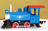
The loco as purchased ?..

Underside ?.
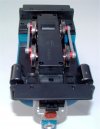

The most obvious discrepancy was the lack of piston rods etc. The moulded plastic incorporates the cylinders/valve chests in one with the frame. The cylinders are open on the insides - so I decided to drill the ends out and insert brass tube inside for the piston rods.
Before I could do this, I had to remove the moulded pips, on the cylinder ends, with a sharp knife (so I could drill through). I used a 4mm drill bit in a Pin Chuck as there was no room for anything powered! Once drilled out, I inserted the tube (cut to the overall outside length of the cylinder), which had one end slightly belled out to stop it shoving right through. I was only moderately accurate with the drilling process!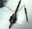
Pips on cylinder ends ?..
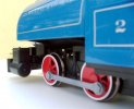

Sleeve(s) in place ?
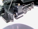
Next I set to and started fashioning the connecting rods, slide bars and slides?..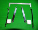
I used some flat mild steel for the connecting rods and some 3.2mm welding electrode for the slide bar (just removed the silica and polished up the rod). The plain end of the slide bars fit into a recess drilled into the cylinder end (on the vertical centre line) and the other end is bolted to the motion cross support using 2mm hex track screws. The cross support was cut from a piece of lipped aluminium strip which was secured to the plastic frame using two 2mm x 6 self-tappers. The piston rods are made from some 2mm dia. bright-coated nails. This gives a sloppy fit inside the brass tube - but compensates for any inaccuracies introduced by my drilling!
The sliders are made from scrap plastic (drilled and tapped 3mm to secure the connecting rods) ? drilled at 3.5mm for the 3.2mm dia. slide bars and 2mm for the piston rods force-fitted. When drilling, the plastic is forced outwards slightly and the resulting hole is slightly less in diameter than it would be drilling into metal ? an ideal result for the interference fit of the piston rod. The 3.5mm slide-bar hole needed reaming out to give the required working fit.
The scrap plastic started out life as protective (transportation) bracket cover on the back of a central heating radiator - yielding strips of 5.5mm x 12mm (cut to required length)?.

Fastening to the wheelset ? plastic retaining plug removed (replaced by a 12 x 3 hardened woodscrew), with a 6mm length of brass tube as a bearing, a 4mm brass nut drilled out to 4mm as a spacer, and washers acting as thrust bearings ?.


Assembly of the motion completed ?..


The next thing was to test it on the track. I used light oil from my set of lubricants, set the chassis on the track ..... and it ran as sweet as a nut. It started to rain so I had to halt the test (didn't want water in the exposed motor and electrics) but will return to testing it as I want to see if the increase in moving parts and friction has any adverse effects on the motor.
This is only the start - I've already removed the moulded-in bell. More to follow ...
I was very pleased with its performance when I reviewed it, but it needed to be lifted from pure toy to something like a model. I couldn?t locate any photographs of a prototype, but having been led to images of larger locos with split tanks, I decided it would remain in that form. Perhaps it should be called Saddle Bags rather than Saddle Tank?
The loco as purchased ?..


Underside ?.


The most obvious discrepancy was the lack of piston rods etc. The moulded plastic incorporates the cylinders/valve chests in one with the frame. The cylinders are open on the insides - so I decided to drill the ends out and insert brass tube inside for the piston rods.
Before I could do this, I had to remove the moulded pips, on the cylinder ends, with a sharp knife (so I could drill through). I used a 4mm drill bit in a Pin Chuck as there was no room for anything powered! Once drilled out, I inserted the tube (cut to the overall outside length of the cylinder), which had one end slightly belled out to stop it shoving right through. I was only moderately accurate with the drilling process!

Pips on cylinder ends ?..


Sleeve(s) in place ?

Next I set to and started fashioning the connecting rods, slide bars and slides?..

I used some flat mild steel for the connecting rods and some 3.2mm welding electrode for the slide bar (just removed the silica and polished up the rod). The plain end of the slide bars fit into a recess drilled into the cylinder end (on the vertical centre line) and the other end is bolted to the motion cross support using 2mm hex track screws. The cross support was cut from a piece of lipped aluminium strip which was secured to the plastic frame using two 2mm x 6 self-tappers. The piston rods are made from some 2mm dia. bright-coated nails. This gives a sloppy fit inside the brass tube - but compensates for any inaccuracies introduced by my drilling!
The sliders are made from scrap plastic (drilled and tapped 3mm to secure the connecting rods) ? drilled at 3.5mm for the 3.2mm dia. slide bars and 2mm for the piston rods force-fitted. When drilling, the plastic is forced outwards slightly and the resulting hole is slightly less in diameter than it would be drilling into metal ? an ideal result for the interference fit of the piston rod. The 3.5mm slide-bar hole needed reaming out to give the required working fit.
The scrap plastic started out life as protective (transportation) bracket cover on the back of a central heating radiator - yielding strips of 5.5mm x 12mm (cut to required length)?.

Fastening to the wheelset ? plastic retaining plug removed (replaced by a 12 x 3 hardened woodscrew), with a 6mm length of brass tube as a bearing, a 4mm brass nut drilled out to 4mm as a spacer, and washers acting as thrust bearings ?.


Assembly of the motion completed ?..


The next thing was to test it on the track. I used light oil from my set of lubricants, set the chassis on the track ..... and it ran as sweet as a nut. It started to rain so I had to halt the test (didn't want water in the exposed motor and electrics) but will return to testing it as I want to see if the increase in moving parts and friction has any adverse effects on the motor.
This is only the start - I've already removed the moulded-in bell. More to follow ...
Last edited:


