Li'l Bash

trammayo

Interested in vintage commercial vehicle, trams, t
Country flag
The loco had been languishing on the bench for four weeks, waiting for my attention. It has been a little too cold of late for working in the shed but I thought I?d have a go at trying to add a few bits (before I became a true couch potato).

I was very pleased with its performance when I reviewed it, but it needed to be lifted from pure toy to something like a model. I couldn?t locate any photographs of a prototype, but having been led to images of larger locos with split tanks, I decided it would remain in that form. Perhaps it should be called Saddle Bags rather than Saddle Tank?

The loco as purchased ?..
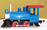
Bash.JPG

4c77e162297a403fbd4f9f9af49172ce.jpg


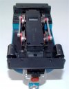
Underside ?.
Bash (2).JPG

f8d176926b164eae811bebc46394f186.jpg


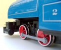
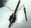
The most obvious discrepancy was the lack of piston rods etc. The moulded plastic incorporates the cylinders/valve chests in one with the frame. The cylinders are open on the insides - so I decided to drill the ends out and insert brass tube inside for the piston rods.

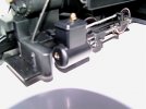
Before I could do this, I had to remove the moulded pips, on the cylinder ends, with a sharp knife (so I could drill through). I used a 4mm drill bit in a Pin Chuck as there was no room for anything powered! Once drilled out, I inserted the tube (cut to the overall outside length of the cylinder), which had one end slightly belled out to stop it shoving right through. I was only moderately accurate with the drilling process!Bash (25).JPG
Pips on cylinder ends ?..
Bash (49).JPG

a99c2e7e41d14baaafb7f654952cb0ef.jpg


Sleeve(s) in place ?
Bash (56).JPG

Next I set to and started fashioning the connecting rods, slide bars and slides?..Bash (4).JPG
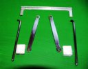
I used some flat mild steel for the connecting rods and some 3.2mm welding electrode for the slide bar (just removed the silica and polished up the rod). The plain end of the slide bars fit into a recess drilled into the cylinder end (on the vertical centre line) and the other end is bolted to the motion cross support using 2mm hex track screws. The cross support was cut from a piece of lipped aluminium strip which was secured to the plastic frame using two 2mm x 6 self-tappers. The piston rods are made from some 2mm dia. bright-coated nails. This gives a sloppy fit inside the brass tube - but compensates for any inaccuracies introduced by my drilling!

The sliders are made from scrap plastic (drilled and tapped 3mm to secure the connecting rods) ? drilled at 3.5mm for the 3.2mm dia. slide bars and 2mm for the piston rods force-fitted. When drilling, the plastic is forced outwards slightly and the resulting hole is slightly less in diameter than it would be drilling into metal ? an ideal result for the interference fit of the piston rod. The 3.5mm slide-bar hole needed reaming out to give the required working fit.

The scrap plastic started out life as protective (transportation) bracket cover on the back of a central heating radiator - yielding strips of 5.5mm x 12mm (cut to required length)?.

638d30c596704ab887b1f74beb772b16.jpg


Fastening to the wheelset ? plastic retaining plug removed (replaced by a 12 x 3 hardened woodscrew), with a 6mm length of brass tube as a bearing, a 4mm brass nut drilled out to 4mm as a spacer, and washers acting as thrust bearings ?.

8ddb7c8015a74c788d3771daf1b884b8.jpg


0c08dec49678405ea222cb943105738c.jpg


Assembly of the motion completed ?..

b8b0d83b5b7c44e2b5c5a2c12b602586.jpg


b1cc7521a6fa40179b76d413ec05ea45.jpg


The next thing was to test it on the track. I used light oil from my set of lubricants, set the chassis on the track ..... and it ran as sweet as a nut. It started to rain so I had to halt the test (didn't want water in the exposed motor and electrics) but will return to testing it as I want to see if the increase in moving parts and friction has any adverse effects on the motor.

This is only the start - I've already removed the moulded-in bell. More to follow ...
 
Last edited:
This has potential.....
 
The loco under test a short while ago. Thomas kept up the chase during the twelve laps but, thankfully, he didn?t ambush it!

668e1b10d94d443fb3295a1b175dd5a1.jpg


The scale mileage completed was three miles or about 730 feet. There was no appreciable rise in temperature although I realise the ambient temperature was around 5 degrees C.


The question of successfully removing the moulded bell without destroying it, or the boiler, needed a little thought. There is no room to get a blade in without damaging either the chimney base (the chimney itself is a push fit) or ragging the tanks. Being a tight git, I wanted the bell intact for remounting on the loco. Then I thought of drilling it out from the underside of moulding. I was lucky to have one or two larger drill bits and found one at 23/32nds that was right.

39d0433635464c3eb872894fd6999f68.jpg


The diameter of the drill needed to be the same (or possibly slightly larger) than the outside diameter of the bell?s moulded base. Also lucky, was the fact that I had reduced the shank of the drill to 12mm so I could ?chuck? it in my small pillar drill. With a block of wood to support the plastic, I carefully drilled through until a hairline gap appeared around the base of the bell.

31d4d1e73f3d43669b85a246a5ede67b.jpg


The bell was carefully parted and squared off on aluminium oxide paper.

5bd5cfaaca944376a271a6124875559a.jpg


Making a bracket and base won?t be a problem for later. Meanwhile I can get on with other things ?..
 
Excellent! Keep it up, we are all looking forward to the finalli.
 
Cool so far looks great, I still have not started my conversion yet. Been too busy with the holiday and such.
 
Thanks for your comments all. I haven't much knowledge of US locos so every little chop is based on different prototypes. Its also an exercise in little or no cost! I fitted knuckle couplings and chopped the pilot boards last night, plus a few other bits. Photos to follow.

I'm thinking of having the smokebox and stack the same colour as the rest of the loco - do you think this would be appropriate?
 
Rob - I should have put that the colour would be black (got a big rattle can from the motor factors).

I like the aluminium finish on the smokebox of my Bachmann locos but, in this case, I don't think it would be quite right for this little engine. The livery, as applied, is a nice colour but somehow seems too much. And the silver finish cuts off on the chimney base which wouldn't be correct.

I remember the silver versus black discussion on here (black for solid fuels and silver for oil) but don't remember any authentic verfication of this.
 
Right then Mick, all black it is!
How about satin smokebox & gloss body?
or
Matt smokebox & satin body?
So many decisions to make!

Right, must get off the computer, there's a HotPot steam-up to atttend.
 
trammayo said:
I remember the silver versus black discussion on here (black for solid fuels and silver for oil) but don't remember any authentic verfication of this.
From personal experience I know that the Ffestiniog painted Linda's smokebox silver for a while shortly after she was converted from coal to oil firing. The reason given was the higher smokebox temperature. However this colour scheme didn't last that long so presumably they managed to source a black that withstood the heat.
 
So black it be.

When I first tested the loco five weeks ago, I fitted a Knuckle coupler on the back. To do that, I had to remove the rear pilot board and fit a Bachmann adaptor (as supplied with Thomas range) to lower the coupling height. After doing this, the pilot board could not be refitted.

As in the real world, these boards were not always the full width of the loco. So I decided to split it ?..

Cut on the red lines ?.

6247c486b3c347a3b1e8b1806f203e2c.jpg


8852880a9974494bafa1851f9912d9a3.jpg


The front end was not supplied with any coupling, but a cursory examination showed there were mounting holes. The pilot board was removed and this left a large square shaped hole. The board also had a small upstand tab which I removed with a horizontal cut so it wouldn?t get in the way of cutting the board into two.

If I?d cut either side of the large square blanking piece, the result would have been a large gap either side of the coupling so I decided to leave as much as I could attached to the, now, two pieces of boards ?

ce88f66e363b4b5ba232e87dcc7daee9.jpg


f11924cf384e49c2885ab1671a43e43c.jpg


With boards reattached things were beginning to take shape?.

9fc55a38b68346f0b39cb4ea29d28257.jpg


The next thing I considered was the working headlight. This, again, is part of the boiler/tanks moulding. However it would not be too difficult to cut off for what I had in mind.

Electric headlight ? where was the generator? On such a small loco, I imagined it would be up top, on the boiler so I set to and cut off the headlamp, leaving the lower part of the lamp mounting on the smokebox top. Care was required in not damaging the wires attached.

The idea was to mount a generator between the chimney and the lamp. A piece of uPVC offcut was drilled for the wires to go through and the lamp was glued down. When dry, the board was glued over the hole and up to the chimney base.

A very basic Pyle turbine dynamo was turned from a piece of dowel. The exhaust was fashioned from a piece of 2mm fence wire. A narrow strip of uPVC was cut to make a mounting for the dynamo and the unit was glued into position??

631b9afafabd41ce88b163952e31755a.jpg


a87b94e1f9c8448194ae65f29b842f6a.jpg


4ff4dbd8fcae4f188eb577ee00a47146.jpg


This is as far as I?m going today because its too cold in the shed ?.
 
I would go all black on the loco. A nice trick is to paint the engine all black. Make the smoke boc, domes dull/flat black. Then add a little shine to the boiler, once dry rub some powdered graphit into the boiler with a piece of paper. Then clear coat on top to hold it in. It will give a nice russian iron look to it. Before the clear coat dries sprinkle a little coal dust on the engine and blow off. Whats left is coal dust in the crevices etc.... Just like the real thing.
 
A very nice Job! Especially for a chap who seemed so reluctant to take a razor saw to his Bachmann tram bumpers.... Not that I should comment I was wondering what "BELL" you were going to remove - ahhhhh that bell, makes a world of difference...
 
Shawn said:
I would go all black on the loco. A nice trick is to paint the engine all black. Make the smoke boc, domes dull/flat black. Then add a little shine to the boiler, once dry rub some powdered graphit into the boiler with a piece of paper. Then clear coat on top to hold it in. It will give a nice russian iron look to it. Before the clear coat dries sprinkle a little coal dust on the engine and blow off. Whats left is coal dust in the crevices etc.... Just like the real thing.

I do have some paint that you polish to give the graphite look. I did think about rubbing some stove blacking in strategic places. Thanks for the suggestions Shawn.
 
tramcar trev said:
A very nice Job! Especially for a chap who seemed so reluctant to take a razor saw to his Bachmann tram bumpers.... Not that I should comment I was wondering what "BELL" you were going to remove - ahhhhh that bell, makes a world of difference...

You're so right (but I have surgically altered two locos in the past - but not the "BELL" before today). But I couldn't have set out on this course of determined loco mutilation if I hadn't been a tram fan:rolf::rolf::rolf::rolf:
 
Yes.... the singing Budgie aka Kylie Minogue will be onto you mutilating "Locomotion"....
I also Liked Shawn's idea.... I'm thinking that the technique would be a novel way to "dirty Up" 4 wheeler side frames....
 
Well today's turned out to be pig (weatherwise). Miserable to start with but, however, the rain desisted for a short while so I ventured into the shed and carried out some further work.

I started by sanding down the front and sides of the tank - firstly to remove the lining out and other tampo printing (which might show through the new paintwork) and, secondly, because I wanted a good key for an area of the loco that would see the most handling. I know there are plastic primers but I?m doing this on a budget and the nearest Halfords is too far away.

6ef319765b1440729d6a13a623587be9.jpg


I then turned a wooden base for the new bell assembly, the latter yet to be made, and it was a nice tight push-fit (through the hole I?d made removing the moulded bell).

My next thoughts were ?how would you fill the tanks with water?? Of course you would have a filler cap and balancing pipe underneath the boiler ? or even two caps! So I searched through the odds and sods, found a couple of plastic caps and, after further searches around the shed, a piece of plastic tube. The caps were a tight fit on the tube which, itself, measured 11mm O.D.

5ede9356bbea49adb120b6acef778a79.jpg


a519b8234f9e4d57b7149f45dbb337eb.jpg


I could have carefully cut and profiled the tube to sit on the tanks but I thought they would stand up to knocks and mishandling better if the tubes were inserted into the said tanks.

315a7da95db5465fa6f5279fd45ff645.jpg


I started drilling, by hand, with a 3mm pilot bit ? drilling radially to the tank?s curvature until I was sure that I had a sufficient start to stop the drill bit sliding off before I returned the drill to the vertical position. I then gradually enlarged the holes using bits increasing by 2mm dia. each time - using a spare drill chuck to hold and control the drilling process. On reaching 9mm, I went up in 0.5mm increments because I didn?t want a sloppy fit as this wasn?t a straightforward drilling exercise.

Once the required size had been reached, the tube was cut to size and inserted into the tanks with a resulting nice tight fit.

8d48b12a63bf446f89b3dc67f1e8bed0.jpg


33ec678632094dc08e26156788c3c1d0.jpg


By this time my fingers were freezing so I called it a day.
 
This very interesting with all the detail and photos of the processes you're providing and she'll be a super little loco by the time you've finished.
 
Back
Top Bottom