Lgb 50950 Colour Light Signal Design

idlemarvel

Neither idle nor a marvel
13 Jul 2015
3,136
801
Ascot
Country
Mars
Best answers
0
Country flag
I recently bought some of these second hand. I am always impressed with LGB build quality and production and these signals are no exception, but the design of the colour switching mechanism leaves something to be desired.

For those who have not seen one of these (pictures below), they use the same point motor base as the semaphore signals, and the same two wire connection to transfer power to the lights, but the weak point is that it uses a magnet fitted to the point motor to trip a reed switch inside the signal mast to switch between red and green. I cannot believe such a mechanism would survive more than a few weeks outdoors. It sort of works, and I can see why LGB have done it, to maintain compatibility with their other semaphore signals, and so they can use the same controls based on isolating tracks etc, but it really is a bit of a poor design IMO.

Base point motor with grey signal mast incorporating reed switch with black magnet block to the right, which slides to and fro driven by the point motor.
IMG_0089.JPG

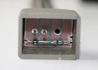
Inside base of signal mast showing two power pins and reed switch.
IMG_0097.JPG

If anyone from LGB reads this forum perhaps they could reconsider the design and for heaven's sake please start using LEDs instead of filament bulbs! :)
 

Railway42

LGB, Radio Control Model Boat, Electronics
28 Feb 2013
430
48
Cheddar
Best answers
0
Country flag
Superb bit of design. The signal motor unit is a well proven design and will last for years.
The clever bit is to change from semaphore to coloured lights. They only designed a clip on
magnet. I have had some of the semaphore signals in the garden for 15-30 years without any
problems. I remove the signal from the base when not in use. A friend of mine has the coloured
light signals in his garden as well for the last 15 years without any problems either. For the
un-technical person it is easier to replace a bulb than if you have to remove a failed LED.
My advice is do not use WD40 as this attracts dirt and causes problems. I pack mine
around the coil with Vaseline and probably service them every two years.
 

idlemarvel

Neither idle nor a marvel
13 Jul 2015
3,136
801
Ascot
Country
Mars
Best answers
0
Country flag
Thanks for the feedback and tips. Completely agree ref point motors and semaphore signals, they are superb. It's just the adaptation to drive the colour signals that I have a problem with. If the design brief was to reuse the semaphore signal kit then it is very clever, ingenious even.
 

cumbrae14

Registered
23 Oct 2011
1
0
Best answers
0
Country flag
Interesting view. I have had these signals in operation for many years and only recently found them becoming faulty. They started to display both lights at the one time and this was identified by a friend of mine as the failure of the relay switch inside the mast. He has renewed several of them for me in recent times with simple replacement relays, but I just leave these technical things to him. He did say however that I should take the signals in when not in use, which I am now doing, so will see if that was the reason for the relay failures. Two signals have become defunct as the slider switch has disappeared on one and the other was run over by a car when I dropped it!! Not sure if this part is obtainable separately, otherwise its two new signals.Can hardly blame LGB for the latter!!
 

playmofire

Registered
23 Oct 2010
8,249
853
80
North Yorks
Best answers
0
Country flag
Two signals have become defunct as the slider switch has disappeared on one and the other was run over by a car when I dropped it!! Not sure if this part is obtainable separately, otherwise its two new signals.Can hardly blame LGB for the latter!!

I may have a spare slider kicking about. I'll try and have a look tomorrow.
 

idlemarvel

Neither idle nor a marvel
13 Jul 2015
3,136
801
Ascot
Country
Mars
Best answers
0
Country flag
Two signals have become defunct as the slider switch has disappeared on one and the other was run over by a car when I dropped it!! Not sure if this part is obtainable separately, otherwise its two new signals.Can hardly blame LGB for the latter!!

I can supply one slider switch and magnet if you drop me a PM I will post to you.
 
  • Like
Reactions: 1 user

idlemarvel

Neither idle nor a marvel
13 Jul 2015
3,136
801
Ascot
Country
Mars
Best answers
0
Country flag
This is how I converted an LGB light signal to LED. Only do this if you don't want to use the filament bulb / motor / magnet / reed switch arrangement described above. But if you do it carefully you could revert back if you needed to.

Dismantle the signal mast and carefully remove wiring from the base and mast, leaving wires attached to filament bulbs which you can keep for spares. The grey top step is unclipped first, and then the side of the mast can be carefully unclipped. The black signal light cover will unclip. The circuit board in the base is extracted by undoing the screw and pulling out the board by the pins. Clip the old wires and unsolder the wire ends and the reed switch from the circuit board.

IMG_0116.JPG

Dismantle signal base, remove motor and slider (top half unclips from bottom half) and keep for spares.

IMG_0123.JPG

Reassemble base without the motor or slider.

IMG_0129.JPG

Use 5mm LEDs, colours to suit your requirement. To make LEDs stay in place cut a thin piece of plastic to fit between the mast head and light cover, with holes big enough to pass the LED leads through but not for the LED heads. You may need to file down the light bulb hole surrounds inside the mast head to allow for the thin plastic so that the signal head cover will still clip into place.

IMG_0120.JPG

I used bell wire to carry power from base to mast head. To make the LEDs easily replaceable I soldered two pins from “dual-in-line” (DIL) sockets at the end of the wires and covered with shrink tubing.

IMG_0135.JPG

The LED leads have to be trimmed.

IMG_0132.JPG

The pins should be plugged into the anode of one LED and cathode of the other, and vice versa for the other LED. This ensures that if the current flows one way, one LED will light, and when the current reverses the other LED will light.

IMG_0122.JPG


Finally the other ends of the wires are soldered to the pins on the tiny circuit board in the base of the mast.

IMG_0119.JPG

The signal can then be driven by a DCC light signal accessory decoder. I used an LDT LS-DEC decoder.

You can use a switch accessory decoder if it can be programmed to continuous output (such as Massoth) but you would need to adjust the output voltage to suit your LEDs and include a resistor in the circuit to protect the LEDs.

Hope this helps someone.
 
  • Like
Reactions: 1 user

playmofire

Registered
23 Oct 2010
8,249
853
80
North Yorks
Best answers
0
Country flag
Two signals have become defunct as the slider switch has disappeared on one and the other was run over by a car when I dropped it!! Not sure if this part is obtainable separately, otherwise its two new signals.Can hardly blame LGB for the latter!!

I've had a hunt round a number of times for the old slider switch I had but without success I'm afraid.
 

idlemarvel

Neither idle nor a marvel
13 Jul 2015
3,136
801
Ascot
Country
Mars
Best answers
0
Country flag
I fitted my LDT LS DEC into an IP55 water proof box from maplins.
I had to trim the central columns out to make room for the board.
IMG_0140.JPG
I connected the appropriate leads to a choc box to make it easier to take the circuit board out in winter.

IMG_0136.JPG
Rather than have a separate 5v DC power supply for the LEDs, you can use the DCC signal which explains the two wires across the circuit board on the left.

The LDT LS DEC uses 8 DCC port numbers in blocks of 4, the first block on the left (top) of the board and the second on the right. In my case they were addressed as 13-16 and 17-20. If you have one, in order to use just two wires to drive the two LEDs in the colour signal, connect them to ports rt1 and gn for the first signal, and gn1 and gn2 for the second signal, and repeat on the other side. Then you can just switch the first colour signal by turning address 13 on and off.
 

NCS from Qbyn

Registered
29 Apr 2016
97
18
70
Queanbeyan, Australia
Best answers
0
Country flag
Interesting view. I have had these signals in operation for many years and only recently found them becoming faulty. They started to display both lights at the one time and this was identified by a friend of mine as the failure of the relay switch inside the mast. He has renewed several of them for me in recent times with simple replacement relays, but I just leave these technical things to him. He did say however that I should take the signals in when not in use, which I am now doing, so will see if that was the reason for the relay failures. Two signals have become defunct as the slider switch has disappeared on one and the other was run over by a car when I dropped it!! Not sure if this part is obtainable separately, otherwise its two new signals.Can hardly blame LGB for the latter!!
Do you know where your friend obtains the replacement relays? I have also had this problem, and Marklin don't seem to offer the relay as a spare part. You can get the light sockets with an attached wire as a spare part from them, but apparently not the relay.
 

Software Tools

Registered
18 Jan 2013
298
52
Sydney, Australia
Best answers
0
Country flag
Do you know where your friend obtains the replacement relays?
The component that is most likely to fail over time is a SPDT (Single Pole Double Throw) magnetic reed switch. Its not a relay.

SPDT reed switches are not hard to find on the electronics supply market, you just need to find one of a size that suits the LGB printed circuit board.

The magnetic reed switch is the glass encapsulated part at the bottom of this photo....

Clipboard01.jpg
 

dunnyrail

DOGS, Garden Railways, Steam Trains, Jive Dancing,
Staff member
GSC Moderator
25 Oct 2009
26,081
4,976
75
St.Neots Cambridgeshire UK
Best answers
0
Country flag
I can understand the confusion here now, if a reed switch has a magnet somewhere ooerating it it sort of becomes a relay, well in operation any way.

My query is what does and how is the reed switch operated. Presumably by some kind of electronically activated/created magnet pulse?
 

idlemarvel

Neither idle nor a marvel
13 Jul 2015
3,136
801
Ascot
Country
Mars
Best answers
0
Country flag
The point motor in the enclosure under the signal moves a magnet to and fro in front of the reed switch, turning the red or green light on alternately.

Quite pleased my one of my threads from 2015 has been resurrected!