LGB 23530 G4/5 tender bulb replacement

phils2um

Phil S
11 Sep 2015
1,522
423
Ann Arbor, Michigan
Country
United-States
Best answers
0
Country flag
I needed to replace the lower right tender lantern bulb in my RhB G4/5. The manual is not correct about how it is done or the specified bulb - at least for the version I have. The manual says to unscrew the lantern housing unplug the dead bulb from the socket and insert a new 5V E130023 bulb. The version I have has 24V, E130110 bulbs that are soldered to the leads coming through the wall of the tender shell. There is extra lead length inside the tender shell but the shell needs to be removed from the chassis in order to access it. The excess is in a twisted loop to keep it orderly. The leads are soldered to the bulb. Pulling some of the extra lead length out of the shell makes it easy to desolder the dead bulb and solder in a new one. Carefully slit the old shrink tube starting at the bulb to get at the solder joints. Don't lose the small O-ring that acts as a retainer to keep the bulb in the lantern housing. Make sure to put it and new shrink tube on the wires before soldering the new bulb. See the attached pic.
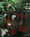
G4-5 tender light - 1 (3).jpeg

While I was working on the lok I also replaced the lower two water level check "valves" that had broken off. I used small brass nails. I chucked the nails in a drill and turned them down to the right size against a file. I also had to turn down the "stem" to fit the original hole. The holes were cleared by hand of the remaining broken "stem" with a small drill in a pin vice. The nails I had on hand were actually brass plated steel. I touched them up with brass Model Master Metalizer Laquer. I'm pleased with how this turned out. The replaced "valves" are the lower two in the next photo.
G4-5 tender light - 1 (5).jpeg

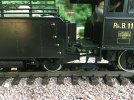
I also made one other visual improvement to the lok that can be seen above. I shortened the lok - tender drawbar length 1 cm by drilling a new attachment hole on the drawbar. I found that this needs to be done on the lok end of the drawbar. I didn't want to cut off the now excess length in case I need to restore it to the the original in the future. There is clearance for the extra length under the lok. There is none on the tender. The tightest curves on my RR are two very short sections with a radius just over that of LGB R2. These were custom bent to make the track fit the location. Otherwise, it is all R3 or greater. The lok still traverses these limiting track sections with the shortened drawbar. It has plenty of clearance.
 
Last edited:

dunnyrail

DOGS, Garden Railways, Steam Trains, Jive Dancing,
Staff member
GSC Moderator
25 Oct 2009
26,171
4,993
75
St.Neots Cambridgeshire UK
Best answers
0
Country flag
I needed to replace the lower right tender lantern bulb in my RhB G4/5. The manual is not correct about how it is done or the specified bulb - at least for the version I have. The manual says to unscrew the lantern housing unplug the dead bulb from the socket and insert a new 5V E130023 bulb. The version I have has 24V, E130110 bulbs that are soldered to the leads coming through the wall of the tender shell. There is extra lead length inside the tender shell but the shell needs to be removed from the chassis in order to access it. The excess is in a twisted loop to keep it orderly. The leads are soldered to the bulb. Pulling some of the extra lead length out of the shell makes it easy to desolder the dead bulb and solder in a new one. Carefully slit the old shrink tube starting at the bulb to get at the solder joints. Don't lose the small O-ring that acts as a retainer to keep the bulb in the lantern housing. Make sure to put it and new shrink tube on the wires before soldering the new bulb. See the attached pic.
View attachment 286538

While I was working on the lok I also replaced the lower two water level check "valves" that had broken off. I used small brass nails. I chucked the nails in a drill and turned them down to the right size against a file. I also had to turn down the "stem" to fit the original hole. The holes were cleared by hand of the remaining broken "stem" with a small drill in a pin vice. The nails I had on hand were actually brass plated steel. I touched them up with brass Model Master Metalizer Laquer. I'm pleased with how this turned out. The replaced "valves" are the lower two in the next photo.

View attachment 286539

I also made one other visual improvement to the lok that can be seen above. I shortened the lok - tender drawbar length 1 cm by drilling a new attachment hole on the drawbar. I found that this needs to be done on the lok end of the drawbar. I didn't want to cut off the now excess length in case I need to restore it to the the original in the future. There is clearance for the extra length under the lok. There is none on the tender. The tightest curves on my RR are two very short sections with a radius just over that of LGB R2. These were custom bent to make the track fit the location. Otherwise, it is all R3 or greater. The lok still traverses these limiting track sections with the shortened drawbar. It has plenty of clearance.
Interesting set of notes for owners. I imagine they will be of use for the Brawa version as well.

A small job worth doing is a tender flap from the footplate, can be done with a small cut-off of of Butyl Pond liner if you have some, if not a bit of bin bag or even black cartridge paper would suffice. Will nicely disguise the wires as well.
 

Monty

Registered
16 Apr 2018
262
56
Springwood, NSW, Australia
Best answers
0
Country flag
Mr Phil S,
As a small deviation to thread, can I ask about the rail hold down method used to retain the track as shown in
the photo of the loco and tender [see below]. It looks ‘interesting’ and something elegant yet mysterious.
Could you please explain…..
thanks
Ian

83D09405-F051-4078-A9B8-C7A178123853.jpeg
 

JimmyB

Now retired - trains and fishing
23 Feb 2018
6,948
921
69
Weston-super-Mare
www.tumble-down-falls.co.uk
Best answers
0
Country flag
Mr Phil S,
As a small deviation to thread, can I ask about the rail hold down method used to retain the track as shown in
the photo of the loco and tender [see below]. It looks ‘interesting’ and something elegant yet mysterious.
Could you please explain…..
thanks
Ian

View attachment 286551
I think you will find that the clamps are providing electrical connection to the track, as opposed to holding the track down.
 

dunnyrail

DOGS, Garden Railways, Steam Trains, Jive Dancing,
Staff member
GSC Moderator
25 Oct 2009
26,171
4,993
75
St.Neots Cambridgeshire UK
Best answers
0
Country flag
I think you will find that the clamps are providing electrical connection to the track, as opposed to holding the track down.
Yup it certainly looks like a Hillman single track feed clamp to me, or maybe a different type of make of Alun Key clamps that are out in the G scale world. However thought is that with some wire bent to fit on the screw and a bigger circle below it could indeed work as a track holding down device, now why did none of us ever think of that before?
 

phils2um

Phil S
11 Sep 2015
1,522
423
Ann Arbor, Michigan
Country
United-States
Best answers
0
Country flag
Hi Monty,

Jimmy and Jon have it right. What you're referring to is a Split-Jaw track power clamp. I've got 12 awg power bus wires buried along most of my line. There are 1/2 m power drops for connection to the rails soldered about every 3 - 4 meters on the bus. Usually a rail clamp was within the reach of the drop. Maybe belt and suspenders but I don't have any voltage drop issues! This drop happened to end right in the middle of a flex-track section hence the need for a separate power feed clamp. Although Split-Jaw sold clamps for attaching power leads this is actually a regular rail clamp that was cut in two.

My track is all free-floating except on the trestle where it is loosely attached about every meter. More info about my RR can be found here if you are interested: Phil S' RR
 

Monty

Registered
16 Apr 2018
262
56
Springwood, NSW, Australia
Best answers
0
Country flag
Hi Phil,

Ah, I didn’t think of that, very clever and obviously effective! Thanks.

Will have a look at your RR link this arvo when I get some spare time.

cheers

Ian
 
8 Mar 2014
7,806
972
San Diego
Country
Armenia
www.elmassian.com
Best answers
0
Country flag
The new owner of SJ asked me about these, I told him they were very handy, he may start making them, I use them to move power through switches, the wires underneath the Aristo switches are crap.

55008575.jpg