I got the LGB 50710 wire holders I was waiting for a couple of days ago. This gave me a chance to finish up the the Infra-red trains sensors I was working on.
Just to catch people up that might not have seen my post on the workbench thread, I am looking to add some automation to my outdoor layout. I am seeking train location feedback that can interface with my Märklin CS3 using its s88 bus. I want to install sensors that will let me control trains without pulling up any existing track. Also, I want to avoid putting in either braking units and/or occupation sensor units and all the associated wiring and required isolated track sections. Finally, I want the sensors to be relatively easy to install and not look completely out of place.
A little more background. I spent quite a bit of time looking at the automation chapters of the CS3 Large Manual, Märklin item no. 03093. From this and the Märklin Digital Dudes Zoom seminars, both of which are primarily geared to the Märklin 3-rail HO system, I came to realize that a track sensor that could give both an "arrival" and a "departure" signal was central to "Events" (automation) programming on the CS3. In the Märklin 3-rail HO system what are called "contact tracks" give the required train arrival and departure triggers to the CS3 s88 bus. I realized an across-the-rails IR sensor could give similar train arrival and departure triggers in the 2-rail world. Azatrax, IR model railroad train detectors, infrared proximity sensors, makes just such an IR train sensor that can be interfaced to s88 bus contact decoders. The only real question was whether the sensors could be made to work on an outdoor layout. Turns out the answer is yes. What happened at your workbench today?
My desire to make the Azatrax IR LED emitter/receiver pairs easy to integrate into my outdoor layout led me to adapt LGB catenary mast bases, No. 56302 and wire holders, No. 50710, to house the sensors. I described how the catenary mast bases were adapted for the IR receivers in the workbench post. This post briefly describes how I put the IR emitters in the LGB wire holders.
First I should mention that reliable arrival and departure triggering relies on sensors remaining triggered without interruption until the entire train has passed the sensors. This is accomplished by locating the IR emitter and receiver pair diagonally across the rails. I found spacing the mast base with the IR receiver three ties from the wire holder with the IR emitter works for me.
On to mounting the IR emitters. First up is a pic of a wire holder with the emitter installed.
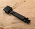
The IR emitter was put in the wire holder so that it was pointed in the general direction of the IR receiver. The rather broad polar intensity pattern of the emitter means it is not critical that the LED be axially aligned with the IR receiver. Still, I tried to keep it close. The next pic shows how I drilled the hole for the body of the IR LED. First I dimpled the location for the hole from head-on to keep the drill from wandering. Then, I mounted a receiver mast and the wire holder to a piece of track. Using the correct size drill mounted in a pin-vice I hand drilled the mounting hole using the receiver mast as a guide.
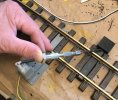
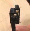
I used a drill bit from a set that I reserve for use on plastic. They stay sharp so hand drilling was pretty easy. After the hole for the body of the LED was drilled I milled out some room for the shoulder of the LED on the back side of the hole. I used a spherical burr in a Dremel tool to do this. This was not a precise operation. I just worked away material until the IR LED slightly protruded as can be seen in the first pic. Once I was satisfied with the fit I put the LED in position and slathered the back side with 5 minute epoxy to permanently keep it in place.
After I had prepared 5 wire holder/emitters (I only bought one package of 5 wire holders - I wanted to be sure I could make them work before spending too much!) I went back to prepping the receiver masts.
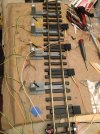
I did these in multiples as can be seen in the above pic. I hooked the emitters and receivers up to the Azatrax module and played with the IR receiver positioning to get them properly aligned to the emitters. I epoxied the IR receivers in place once I was satisfied. As can be seen, I also filled the remainder of the "H" slot in the catenary base with epoxy too.
Here's a pic of a finished emitter receiver pair mounted to a piece of track.
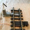
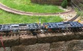
Finally, the IR sensors passed the acid tests, a last check outside in bright sunshine using worst case test wagons - unloaded LGB container cars:
Then I remembered these!:
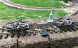
It was serendipitous that the disconnect drawbar just happened to block the receiver's view of the emitter too!
Now I've got all the IR sensor and s88 bus hardware worked out and tested all I need to do is figure how to implement my train control logic.
Piece of cake! - yea right!
Just to catch people up that might not have seen my post on the workbench thread, I am looking to add some automation to my outdoor layout. I am seeking train location feedback that can interface with my Märklin CS3 using its s88 bus. I want to install sensors that will let me control trains without pulling up any existing track. Also, I want to avoid putting in either braking units and/or occupation sensor units and all the associated wiring and required isolated track sections. Finally, I want the sensors to be relatively easy to install and not look completely out of place.
A little more background. I spent quite a bit of time looking at the automation chapters of the CS3 Large Manual, Märklin item no. 03093. From this and the Märklin Digital Dudes Zoom seminars, both of which are primarily geared to the Märklin 3-rail HO system, I came to realize that a track sensor that could give both an "arrival" and a "departure" signal was central to "Events" (automation) programming on the CS3. In the Märklin 3-rail HO system what are called "contact tracks" give the required train arrival and departure triggers to the CS3 s88 bus. I realized an across-the-rails IR sensor could give similar train arrival and departure triggers in the 2-rail world. Azatrax, IR model railroad train detectors, infrared proximity sensors, makes just such an IR train sensor that can be interfaced to s88 bus contact decoders. The only real question was whether the sensors could be made to work on an outdoor layout. Turns out the answer is yes. What happened at your workbench today?
My desire to make the Azatrax IR LED emitter/receiver pairs easy to integrate into my outdoor layout led me to adapt LGB catenary mast bases, No. 56302 and wire holders, No. 50710, to house the sensors. I described how the catenary mast bases were adapted for the IR receivers in the workbench post. This post briefly describes how I put the IR emitters in the LGB wire holders.
First I should mention that reliable arrival and departure triggering relies on sensors remaining triggered without interruption until the entire train has passed the sensors. This is accomplished by locating the IR emitter and receiver pair diagonally across the rails. I found spacing the mast base with the IR receiver three ties from the wire holder with the IR emitter works for me.
On to mounting the IR emitters. First up is a pic of a wire holder with the emitter installed.

The IR emitter was put in the wire holder so that it was pointed in the general direction of the IR receiver. The rather broad polar intensity pattern of the emitter means it is not critical that the LED be axially aligned with the IR receiver. Still, I tried to keep it close. The next pic shows how I drilled the hole for the body of the IR LED. First I dimpled the location for the hole from head-on to keep the drill from wandering. Then, I mounted a receiver mast and the wire holder to a piece of track. Using the correct size drill mounted in a pin-vice I hand drilled the mounting hole using the receiver mast as a guide.

I used a drill bit from a set that I reserve for use on plastic. They stay sharp so hand drilling was pretty easy. After the hole for the body of the LED was drilled I milled out some room for the shoulder of the LED on the back side of the hole. I used a spherical burr in a Dremel tool to do this. This was not a precise operation. I just worked away material until the IR LED slightly protruded as can be seen in the first pic. Once I was satisfied with the fit I put the LED in position and slathered the back side with 5 minute epoxy to permanently keep it in place.

After I had prepared 5 wire holder/emitters (I only bought one package of 5 wire holders - I wanted to be sure I could make them work before spending too much!) I went back to prepping the receiver masts.

I did these in multiples as can be seen in the above pic. I hooked the emitters and receivers up to the Azatrax module and played with the IR receiver positioning to get them properly aligned to the emitters. I epoxied the IR receivers in place once I was satisfied. As can be seen, I also filled the remainder of the "H" slot in the catenary base with epoxy too.
Here's a pic of a finished emitter receiver pair mounted to a piece of track.

Finally, the IR sensors passed the acid tests, a last check outside in bright sunshine using worst case test wagons - unloaded LGB container cars:

Then I remembered these!:

It was serendipitous that the disconnect drawbar just happened to block the receiver's view of the emitter too!
Now I've got all the IR sensor and s88 bus hardware worked out and tested all I need to do is figure how to implement my train control logic.
Piece of cake!
Last edited:
