High Density Flexible HDPE Ladder Roadbed, Wood Trestles & Bridges

John Carmichael

Registered
Country flag

Modern Flexible HDPE Ladder Roadbed, Wood Trestles & Bridges


This how-to video describes our modern flexible HDPE (High-Density Polyethylene) ladder roadbed, redwood timber trestles and bridges for the Cholla Patch Railroad in Tucson AZ. I highly recommend this type of roadbed for its ease and speed of construction, low cost, durability and beautiful curves.

Our non-traditional flexible roadbed is made from 3/4" thick HDPE house siding ripped into 20ft. long thin strips. I made the roadbed by attaching two HDPE strips together using short pieces of composite wood that I call "brownies". Video has useful design plans, graphics and assembly photos, and shows the advantages of this modern roadbed construction design. All the wood pieces are redwood, stained and sealed with Minwax dark walnut stain before assembly, then glued together with Titebond III secured with solid Brass Escutcheon pins (brads). I made printed templates of the pieces needed for everything. I attached the template drawing of the biggest trestle to particle board, making a sturdy wood jig for easy assembly. Wood is re-stained about every four years. I think you'll also enjoy seeing the detailed and extensive wood trestles and cool wood Bridges.

Feel free to copy, use or modify any of the images or video shorts you see here. I highly recommend this type of roadbed. I hope this helps you make your decision on the type of roadbed and materials you'll use for your own garden railroad. - John Carmichael

See my other projects here Cholla Patch Garden Railroad Design & Construction Series:

Cholla Patch Garden Railroad Design & Construction Series
 
Last edited:
Looks very similar to Filcris, which works well, if you can overcome the expansion/contraction.
As an aside, I know a chap who is using aluminium ladders for the straight runs on his layout
 
Looks very similar to Filcris, which works well, if you can overcome the expansion/contraction.
As an aside, I know a chap who is using aluminium ladders for the straight runs on his layout
Looking at the price of Filcris, it is not cheap!
 
Looking at the price of Filcris, it is not cheap!
Abreed, this is one if those products that using un recyclable products should have environmental price benefits for the manufacture and sale of the products.
 
Looking at the price of Filcris, it is not cheap!

Looks very similar to Filcris, which works well, if you can overcome the expansion/contraction.
As an aside, I know a chap who is using aluminium ladders for the straight runs on his layout
I wholly concur about the expansion issues with Filcris - I have had to abandon its use on my railway because it wouldn't stay put.
 
Don't use Filcris for the stringers of a flexible ladder roadbed. Filcris is NOT flexible enough and will not bend well for making curves. Filcris is more like a composite wood and has structural strength. HDPE is sold as non-structural house siding- like vinyl siding. That is why it bends so well. BTW, if you can't find HDPE house siding, you can use vinyl siding instead. It is a little more flexible, but is not quite as durable as HDPE.

TrexTrim is the material I used. It is PVC lumber but is very similar in all ways to HDPE lumber. It’s very flexible, but I don’t know if it is more or less flexible than HDPE. I bought this size: SKU: WW010618B. This measures: 3.4” thick x 5.50” wide x 18 ft. long (actual). It’s white with wood grains. I had the supplier rip each board into 1.75” strips for the stringers. Wider boards are available but all will need ripping. The supplier delivered the ripped strips to my home for a small fee. Website: Trex trim brochure - Trex Inc. - PDF Catalogs | Documentation | Brochures
 
Last edited:
Filcris does work very well providing you accept what you are going to be faced with in terms of expansion. Track not too severely pinned or screwed down works very well. I have a short section that gets early sun and mives around a lot and this is on wood! To keep track in place I have oblongs of HIPS pinned in the centre of sleepers, this is smaller than the oblong that it sits in thus allowing the track to move in all directiins. As all track is held with Clamps that movement causes no issues as it is contained withing the track and board limits.
 
Mine seems to work well
Hi Dunnyrail:
Your statements raised more questions than answers for me. I admit I'm not familiar with Filcris. Please tell us more.
Questions:
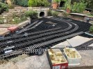
My concern about using Filcris stringers in a flexible ladder roadbed is its lack of FLEXIBILITY IN CURVES. Do you use it where you have small curve radii? If so, what is the smallest curve radius you have? Also, how thick is one of your Filcris stringers.? My HDPE has 3/4" thick stringers and the smallest radius I could make is about 4 ft. for my trolley line. (see roadbed photo below). Can your Filcris bend this tightly? When you buy the Filcris, what is the size boards you buy (length, width, height? And what are the dimensions of your stringers after you cut them to size?

Thank you for your comments and please pardon all the questions- John Carmichael
 

Attachments

  • DSC00467 - Copy.JPG
    DSC00467 - Copy.JPG
    589.9 KB · Views: 6
Last edited:
Websites on Post & Ladder Open Stringer Roadbeds:
Here is the VERY informative article about a Columbus-area architect named Bill Logan who in 2002 began developing the construction method for I used for my raised HDPE flexible roadbed. I located the original online article that taught me about his “post and ladder” flexible roadbeds. It was a game-changer for me when I read it years ago. This brilliant innovator, Bill Logan was my mentor and unsung hero! Thank goodness I read this BEFORE I designed and built anything.

This 4 part article series is the best online information I can find on ladder stringer roadbeds. It describes inventor Paul Logan’s flexible stringer and post construction method. It’s often called the “Post & Ladder” method. This was the basis for my own railroad. I modified slightly Mr. Logan’s design and construction technique to improve strength, facilitate cutting, and allow a hidden place to run electrical lines:

Here it is!
https://familygardentrains.com/primer/roadbed/ladder1.htm
HDPE Flexible Roadbed Method - Part 2
HDPE Flexible Roadbed - Part 3

In short, his revolutionary construction method involves the use of HDPE (high density polyethelyne) in what its inventor, Bill Logan, describes as an “open stringer”. He calls it the flexible post and stringer method. Mr Logan says “it still uses posts and stringers, but the finished installation looks far more "open" from above. In fact, the roadbed looks something like flexible "ladders" for which the "rails" and "rungs" are prepared in the shop and assembled to fit onsite.” Now, it’s often called a “Post & Ladder” Roadbed.

See the following video showing the great load bearing strength of one man’s post and ladder roadbed. Note the wide 4 to 6 ft. spacing of the support structures. The HDPE ladder roadbed between supports doesn’t even sag under the heavy weight train engine! Even so, a closer maximum spacing of 2 ft. would be much better. Also note the unsightly placement of the electrical conduit line tied to the bottom side of one of the stringers. A much better place to place the electrical lines is to hide them between the rails just under the ties in the small ¼” space above the stringer connector/spacer blocks in my design:
 
Last edited:
Hi Dunnyrail:
Your statements raised more questions than answers for me. I admit I'm not familiar with Filcris. Please tell us more.
Questions:
My concern about using Filcris stringers in a flexible ladder roadbed is its lack of FLEXIBILITY IN CURVES. Do you use it where you have small curve radii? If so, what is the smallest curve radius you have? Also, how thick is one of your Filcris stringers.? My HDPVC has 3/4" thick stringers and the smallest radius I could make is about 4 ft. for my trolley line. (see roadbed photo below). Can your Filcris bend this tightly? When you buy the Filcris, what is the size boards you buy (length, width, height? And what are the dimensions of your stringers after you cut them to size?

Thank you for your comments and please pardon all the questions- John Carmichael
I have never used the Filcris ladder section but built a Garden Railway for a buddy using their Decking planks. Later we covered them with a product called ‘Eco Board’ that has much less issues with expansion. This stuff if a light colour and appears to be made from stranded plastic glued together rather than melted plastic that Filcris appears to be made of being a uniform Brown or Black colour. I am pretty sure that you would be able to get the curves to 4ft radius as some if the lines I have seen it on appeared to be a little smaller than this, perhaps users in the forum could comment re radius achievable.

Another option may be to look at the products used for Barge Boards on houses, this I have used for Concreteting sub-bases and does bend quite to small radius and has much less issues in expansion. There are quite thin and thicker options available UK, the thiner for the outside and the thicker for the cross beams to enable screws to be used. You would of course need to extensively cut things to get to the size you need, a bench saw used withncare and slowly ought to work and give the accuracy required. Again I have nit used it on my line being either wood ir concrete, bricks, paving slabs for my line.
 
I beg your pardon as I must admit a big mistake. I'm not a chemist, I mix up chemical names- and I'm old. I told you incorrectly that I used HDPVC (High Density Polyvinyl Chloride), but it was actually HDPE (High Density Poly Ethelyene). I just plain forgot the name.

TrexTrim
is the material I used. It is PVC lumber but is very similar in all ways to HDPE lumber. It’s very flexible, but I don’t know if it is more or less flexible than HDPE. I bought this size: SKU: WW010618B. This measures: 3.4” thick x 5.50” wide x 18 ft. long (actual). It’s white with wood grains. I had the supplier rip each board into 1.75” strips for the stringers. Wider boards are available but all will need ripping. The supplier delivered the ripped strips to my home for a small fee. Website: Trex trim brochure - Trex Inc. - PDF Catalogs | Documentation | Brochures

Please excuse me! I'll try to fix this mental typo error by editing my previous posts.
 
Last edited:
HDPE (high-density polyethylene) roadbeds are made from very flexible high-density UV-treated PVC sold for house siding. UV-treated vinyl can also be used, but is less flexible. It’s available with faux wood grain and is ¾” thick. The lumber yard ripped many 18 ft. long 1 ½” wide strips for me. Two 18 ft. stringers screwed together back-to-back form a 18 ft. section of ladder roadbed by screwing 2 ¼” x 1 ¼” x 1 ¼”” composite wood spacers (we call them “brownies”) between the stringers every 6”. Its flexibility automatically forms perfect curves of the desired radii between any three points. Before joining with brownies, a single stringer can be bent into almost any curve, even tight R3 radii. After joining, both stringers become rigid and hold the desired shape. Stringers are connected end-to-end with 8” long pieces of HDPE screwed to abutting stringers. Position and join all stringers on the ground, then raise the entire joined roadbed little by little to the correct heights indicated by SCARM (a great track design app). Temporary vertical posts support it every 6 feet.

Now paint the roadbed. Sun eventually destroys plastics, even UV-protected ones. For extra protection and aesthetics, paint HDPE with primer and with two coats of desired color. After painting with Krylon flat dark brown spray paint for plastics, I removed the temporary vertical posts and replaced them with wood trestle bents using steel angle brackets. Then I bent the rails and attached the track. The roadbed is 3 ½” wide, matching LGB ties which are screwed to it. Use countersunk waterproof deck screws for the ladder brownies and joiners, and ¾” stainless steel tiny rounded screws for ties. Note: For strength, do not put stringer abutment joiners across from each other. Stagger them.
 
Last edited:
I have never used the Filcris ladder section but built a Garden Railway for a buddy using their Decking planks. Later we covered them with a product called ‘Eco Board’ that has much less issues with expansion. This stuff if a light colour and appears to be made from stranded plastic glued together rather than melted plastic that Filcris appears to be made of being a uniform Brown or Black colour. I am pretty sure that you would be able to get the curves to 4ft radius as some if the lines I have seen it on appeared to be a little smaller than this, perhaps users in the forum could comment re radius achievable.

Another option may be to look at the products used for Barge Boards on houses, this I have used for Concreteting sub-bases and does bend quite to small radius and has much less issues in expansion. There are quite thin and thicker options available UK, the thiner for the outside and the thicker for the cross beams to enable screws to be used. You would of course need to extensively cut things to get to the size you need, a bench saw used withncare and slowly ought to work and give the accuracy required. Again I have nit used it on my line being either wood ir concrete, bricks, paving slabs for my line.
Hello Dunnyrail:
Could you possibly share a photograph of your roadbed so I can see what we are discussing? "A picture is worth 1000 words".

Thanks!
 
Hi Paul:
Would you please share a photo with us if you have one? I'd love to see what we're discussing. "A picture is worth 1000 words".

Thanks!
To be honest, the road bed is invisible as it's ground level up to the deck and is covered in roofing felt. The track itself is only held down on the curves, leaving the straight lengths free to expand/ contract. In the recent heat, there has been no problems with the track work
 
Hello Dunnyrail:
Could you possibly share a photograph of your roadbed so I can see what we are discussing? "A picture is worth 1000 words".

Thanks!
Your wish and all that.

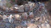
First is a curve, rebuilt from a wood construction. There are bricks to the front with building blocks to the rear. The surface is cut paving slabs around 9/12 inches. In the middle are old Bags used for 1 ton building supplies filled with large rubble from a drainage job, nothing goes out in skips here. Topped with weed fabric and decent soil on top for planting.IMG_9383.jpeg
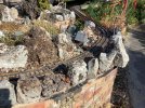
Next is a Station area much the same construction but with 2ft paving flags for a Station Area, where the building bit is 4ft wide. Bricks to front then 3 separate rows of building blocks again gaps filled with rubbish and clay from foundations. Oh yes I make foundations to match any grades, the curved section is roughly 1 inch in 48 inch rise.
IMG_9385.jpeg
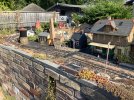
Next up the boards and Station recovered from my pals line (higher ones lower was my addition) , these are all on Decking Planks with decking planks end on for edge and some centre support. The lower level is on 8 x 2 inch Roofing Joists gifted by a neighbour after many years of outside storage in his garden.
IMG_9384.jpeg
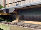
Below, both boards are my former and still occasionally used build with Wood Tantalised Gravel Boards (used beneath fences at times), the surface is 6 inch with the support being same Gravel Boards being cut to half width. Some of this recovered from another pals line and is now over 3 decades old, original preservation with Creosote (banned in UK for many years) and now with good quality felt on top and sides to just below sides so that water does not capillary up onto the wood below. This method clearly stands the test of time, particularly if you use Roofing Felt Mastic at joints and where screws go through track into the wood. Also you can see some short ally sections separated with 8mm screw rods with nuts and washers. L ally angle at edges.

IMG_9386.jpeg
Much of this can be seen in build on my thread linked in blue below except where many of the old pictures have been lost in some Forum updates. I keep meaning to go through to put the pics back, but one of those ‘Round To It Jobs!’.
 
Just offering another product which can be used beneath tracks, as in the UK we appear to be bit more limited in what plastic raw materials are readily available. These are clip-together plastic grid squares, sold as shed base or for use beneath resin paving. In this example, at ground level, they are sitting on old paving slabs, but of course could be used for raised tracks. Once wiring and the watering system were put in, the grids were filled with gravel and a heavy duty PVC membrane was laid on top, for the track and scenery to sit on.
IMG_3024(1) (Medium).JPEG
 
Thank you for the photographs. They answered several questions I had about your roadbed. I see why I was confused. I thought that you had a flexible ladder railroad similar to mine. So I didn't understand your setup. Your new comments and photos explained everything. Thank you! I see now that you were talking about a completely different type of construction

I was intrigued by the materials you used.- especially the use of felt for drainage. I have never seen that before- it must be a British thing. I like the idea of "Gravel Guards" for elevated stringer roadbeds on posts. I can envision HDPE flexible ladder roadbed modified so that it becomes the Gravel Guard. The roadbed would be just gravel for floating track, or the ties could be attached in some way to the stringer connectors. In such a design, the stringers would be taller than my design (to hold in the grave), and would have much more separation to accommodate realistic ballast.- like your design does. A 1/4" rust proof sturdy screen mesh to hold the gravel would rest on the stringer connectors". It's neat idea. It could even work on trestles and bridges I think. I don't think I've ever seen gravel guards in any garden railroad in our area. Is it common where you live?

Thanks again for going to all that effort to send the photos and write your interesting comments. And by the way, your railroad is charming!- John Carmichael
 
Last edited:
Post & Ladder Stringer Roadbeds - Construction Steps
From unpublished article by John Carmichael - Feb 2, 2019 - Tucson AZ

Suggested Step-by-Step Construction Instructions:
1) Prepare the Roadbed Site:
Just clean up general debris and things you know you need to remove for the roadbed. It is not necessary to remove all the plants and rocks. I would avoid doing any major landscaping at this stage. Just rake the ground and remove rocks where you are pretty certain the route would go.

2) Determine the Routing Design of your Layout. You do not necessarily need to make a precise drawing of the layout using this method and you don’t need templates. Use garden hoses instead! (However if you want a site plan drawing of the railroad, try using this free layout design software. It’s easy and intuitive: SCARM - The leading design software for model railroad layouts) Using the hose method is fun, so get the whole family involved. When it’s sunny and warm and the hose is flexible, lay a hose of known length (or several connected together) flat on the ground of the site following your general roadbed route avoiding special plants and other non-movable structures. Remove anything that’s in the way that you are willing to sacrifice. Play around with the routing until everybody is happy with the general design. The hose placement does not need to be exact, only approximate. But remember one of the cardinal rules of model railroads: Make the curves as wide as possible! You can measure radii exactly if needed with a center post and a tape measure or string or by comparing a section of factory track curves to the hose. Where tracks cross at different elevations, just let the top hose lie on top of the hose underneath. Don’t worry about elevations for now.

3) Determine the Linear Feet of Roadbed in the Design: Add up the total length of the hoses you used. Easy! This will give you a close estimate of the linear feet of roadbed you will need.

4) Calculate the Total Linear Feet of Lumber Required: Using my design drawings and measurements, calculate the total linear feet needed to make the HDPE flexible stringers (both sides of the ladder) and the composite brownies. Since everybody has different elevations, you will need to estimate the total footage of 2 X 2 composite stock needed for the elevation posts and add that to the stock needed for the brownies because you’ll make the posts and brownies out of the same stock. The average height of your railroad multiplied by the number of posts roughly equals the total footage of post stock. If you only need posts temporarily until you install trestles, then put the posts 6ft. apart. But if the posts will be permanent then place posts 2ft. apart. Add about 25% extra stock to all your calculations.

5) Locate Suppliers: Besides pricing and availability, try to find ones who will rip the stringers if needed and will deliver your order to you. The stringer lumber requires a very long flatbed truck! My supplier only charged me 75 dollars for the delivery. 8 to 12 ft. long composite stock is a convenient length to buy for the brownies and posts.

Find the longest lengths available of flexible HDPE or PVS for the stringers. (see suppliers list below)

6) Purchase Supplies: Of course price is important, but as I told one member, I would use this method and these materials even if they were a little more expensive than others because there are so many extra benefits. Be sure to buy about 25% extra materials to cover Murphy’s law. You’ll be glad you did! Note that actual lumber sizes are often different from nominal sizes. Also, buy a couple boxes of 1 5/8” Deck Screws at Home Depot to get you started. I like the flat head Philips screws by Everbuilt which come in grey and brown, but color doesn’t really matter since you’ll be painting the final assembly.

7) Prepare your Shop or Garage for Pre-construction: You will need a place to cut wood accurately with a table saw or a cut-off saw fitted with large teeth blades to avoid overheating plastic. Avoid hand-held saws for more accurate cuts. You’ll need a sanding block or palm sander for rough edges. An electric screwdriver is essential to protect your hands from strain. And you’ll need several clamps. I love the Quik-Grip mini bar clams. Metal “C” clamps are good too, but require extra padding so they don’t damage the HDPE. You need a tape measure, a yardstick type ruler, a handheld electric drill and a long workbench or table to hold the 8 ft. long stringer jig template. A 9 or 10 foot bench would be best. If you don’t have a bench you could clamp the jig on top of two sawhorses. Make the brownie jig using the drawing (see jig drawing below).

8) Make the Brownies: One roadbed builder affectionately called the stringer spacer/joiners blocks “brownies”. That’s exactly what they look like, and that’s what I call them. When I made the “brownies” it was a real assembly line. I felt like Lucy Ball at the chocolate factory! I’d cut hundreds at a time filling up a couple of big buckets with them. The bench supported the 12 ft. long composite stock as I cut it down with my table saw at the end of the bench. Use a chop saw or table saw with blades with large teeth to avoid plastic melting. Use 1.5" x 1.5" actual size composite wood stock. Be careful with your cuts so that each brownie is exactly 2” long and the cuts are straight by using the saw’s sliding board guide. It’s easy to get sloppy when you make so many and are cutting them quickly. Avoid hand-held saws since they don’t cut as straight as a table or chop saw. Since there are two brownies per foot on the stringers, the total number of brownies needed is 2 times the total linear feet of roadbed. Example: If you have a 100 ft. roadbed, you’ll need about 200 brownies.

9) Partially Assemble the Stringers: During in-shop pre-construction, using the brownie jig, only attach one side of the “ladder” stringer to the brownies. First measure and mark the drill hole locations on a stringer board with a Sharpee pen. Then insert brownies into the jig notches and clamp one flexible stringer board to the front. If it has wood grain, make sure it’s on the outside. The hole mark should be exactly in front of the center of each brownie. While still clamped to the jig, drill pilot holes about 1 5/8” deep through the stringer and into the brownies. Make pilot holes smaller than the diameter of the deck screws. I used 1/8” drill bits. Since the HDPE is somewhat soft, you can tighten the screw way down so that the screw head is countersunk and flush with the surface of the stringer. It’s ugly if it sticks out. Remove the partially built stringer and brownie assembly from the jig, and place it back into the jig to finish attaching all the brownies along the entire length. Do not connect the other half of the stringer assembly until the on-site construction phase. Add up the number of butt joints you’ll need, then using the same 1.75” wide HDPE stringer material, cut 6” long lengths that will serve as the stringer butt end joiners. Add one joiner to one end only. Don’t add joiners at both ends! Remove partial stringer assembly and store it out of the way. Continue making and storing more partial stringer assemblies. The total length of the partially assembled stringers is equal to half of the total length of the entire roadbed. (See stringer drawing below).
Note: The roadbed for switches and multiple tracks must be made separately without a jig. (See switches and multiple track drawing below)

10) Begin On-Site Partial Stringer Assembly: Now it’s time to connect the ends of the partially assembled stringers (half of the ladder). This part is real fun! Drag two partially assembled stringers to the construction area (they are too floppy and unwieldy to carry.) Lie them end-to-end on the ground right next to your garden hose “template”. To connect the butt ends of the stringers together, use two 1 5/8" Deck Screws on each stringer placing them 1" and 2" from the ends of the stringers. Each butt joint requires 4 screws total. (See stringer drawing below) Pound rebar into ground next to the stringers to maintain the curves you want. You can also use bricks or rocks if you run out of rebar. Watch how the stringers magically pick the best curves with perfect transitions- even S-curves! All you need to do is find the biggest curves that fit in the available space while avoiding obstacles. Then repeat this over and over as you extend the partially assembled roadbed. Don’t worry about elevating them now. Just leave them on the ground. Where one partial roadbed passes over another, just let it temporarily rest on the stringer below it. We are only concerned with the shape of the route at the point.

11) Finish Stringer Ladder Assembly: After you are completely satisfied with the shape and you like the curves, it’s time to attach the opposite stringers of the ladder to the partially assembled stringers on the ground. Drag several stringers boards without brownies to the railroad site. When you attach the opposing stringer boards, the structure magically becomes very rigid! You cannot change the curve while both sides of the ladder are attached to the brownies. If you find you need to change the curve you can simply unscrew one side of the ladder to readjust. It's extremely important to stagger the placement of the stringer butt joints so that there is no joint on or near the opposite side of the ladder. This would weaken this section of roadbed and will cause crimping in a tight curve. Don’t put joints across from each other! Leave the fully assembled roadbed on the ground until the next step.

 
Last edited:
Back
Top Bottom