Fitting LGB 21761 "Spremberger" 0-4-0T with decoder

idlemarvel

Neither idle nor a marvel
13 Jul 2015
3,136
801
Ascot
Country
Mars
Best answers
0
Country flag
This model of steam locomotive #2 of the Spremberger Stadtbahn was produced in three different versions by LGB:
In 2001 - With decoder interface only.
In 2002 - With decoder interface and factory installed 55021 decoder.
In 2003 - With installed 'on-board' decoder.

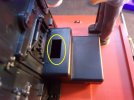
Mine is a "2001" model (date stamped 01/01/01!). To open her up, there are only two screws, although they are awkward to get to because of the running gear. Then undo the clip at the front under the smokebox door and it "flips back". This is easier if you remove the clip on brake pipes first, front and rear.

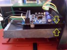
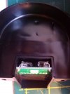
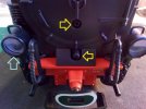
EDIT: pictures added below. First shows location of screws, second the front clip and third the hinge point.
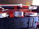
IMG_20200929_105550.jpg
IMG_20200929_105639.jpg
Note: the screw marked with the ywllo arrow holds the clip in place, I plan to remove these as they are hardly prototypical! Also I have added the headlight rims (blue arrow).
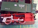
IMG_20200929_105754.jpg

Once the top is off the next tricky bit is to remove the weight. You think there are just two screws but there is a hidden screw underneath fixing the circuit board to the bottom of the weight, so you have to unscrew the circuit board as well.
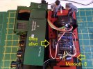
Inside there is an old fashioned circuit board (see picture). There are four black wires soldered to it for the front lights (5v bulbs), two pins for the black and white cables for the smoke generator (5v), and a 5-pin socket, with white, green, yellow, gray and red ribbon cable. The red and gray go to the multi-purpose socket at the rear of the loco, the white is for the rear lights, green for the cab light and yellow is the common. The lights are all 5v bulbs.
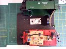
IMG_20200920_105504.jpg

There is also a 6-pin decoder socket so with an old 55021 decoder and a 6-pin interface cable you could quickly install a decoder which was of course the intention at the time. I happened to have a spare XL decoder so it was easier just to strip out the old circuit board and wire up the decoder directly. I unsoldered the front lights and removed the board and associated wiring. Then I attached yellow, white, brown and green cables to the motor block pins (see picture), replaced the weight, ran the cables underneath the weight and attached them to the XL decoder. I covered the top of the weight with insulating tape and screwed the decoder onto the weight (see picture). Time to test the motor. Always best to test on programming track first to make sure there are no short circuits.
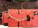
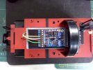
IMG_20200920_112448.jpg
IMG_20200920_144005.jpg

Then I attached the light and smoke generator wires as follows:
smoke generator (black) and two of the front light leads (one from each light) into +22
  • the other two front light leads into LI-V
  • yellow from motor block into MOT+
  • white from motor block into GL+
  • brown from motor block into GL-
  • green from motor block into MOT-
  • white from 5 way ribbon cable into LI-H
  • smoke generator (white) into A1
  • yellow from 5 way ribbon cable into +22 (the other one)
  • green from 5 way ribbon cable into LI-I
Before testing the lights you need to adjust the voltage as the Massoth default is full track voltage. Set CV 50 to 5 for the lights (bit less than 5 v) , and CV 54 to 8 for A1 (aux 1) voltage as I found the smoke generator works better with a little bit more than 5v. I also set CV 55 to 7 to make the command for A1 (aux1) to be F7, which is the Massoth default for smoke generators. Other CVs are left at the default settings at this stage, except perhaps CV 29 set to 2 if you want more than 14 speed steps (or 6 if you also want analog option). I also halved the max speed CV5 from 255 to 128. Reassemble the loco and test. Next step in a future posting is to add sound.
 
Last edited:

AustrianNG

Director of my railway
16 Sep 2015
1,397
1,721
Wirral
Best answers
0
Country flag
Nice one. Are you going to add weight to give the little fella a bit more grunt ?
 

Zerogee

Clencher's Bogleman
25 Oct 2009
17,351
1,723
North Essex
Best answers
0
Country flag
............ Next step in a future posting is to add sound.

As the XL you've used has a SUSI socket, maybe either a Dietz/Uhlenbrock sound module or else one of these from MD mXion....


Much cheaper than a Massoth S... I've not used one myself yet, but am planning to get and try a couple of them out soon.

Jon.
 

Markku

Registered
19 Jul 2020
28
6
Finland
Best answers
0
Country flag
There are four black wires soldered to it for the front lights (5v bulbs), two pins for the black and white cables for the smoke generator (5v), and a 5-pin socket,

I wonder if I have to adjust the smoke generator voltage of my Stainz decoder fitting as well: The Puutarharata - G Scale Central (Massoth Emotion L) How do I know what is the voltage of the smoke generator in Stainz?
 

AustrianNG

Director of my railway
16 Sep 2015
1,397
1,721
Wirral
Best answers
0
Country flag
I wonder if I have to adjust the smoke generator voltage of my Stainz decoder fitting as well: The Puutarharata - G Scale Central (Massoth Emotion L) How do I know what is the voltage of the smoke generator in Stainz?

In short Yes. The starter set locos have the 16/17 volt smoke unit, but the Massoth decoder units are factory set to full track voltage of around22-24 volts.
You can tell the voltage of your smoke unit as follows:
Black and white wires - 5 volts
grey and black wires or yellow and brown wires - 16 volts
White wires - 22 volts

I think..........someone will correct me if the colours are vice versa !
 

Markku

Registered
19 Jul 2020
28
6
Finland
Best answers
0
Country flag
In short Yes. The starter set locos have the 16/17 volt smoke unit, but the Massoth decoder units are factory set to full track voltage of around22-24 volts.
You can tell the voltage of your smoke unit as follows:
Black and white wires - 5 volts
grey and black wires or yellow and brown wires - 16 volts
White wires - 22 volts

I think..........someone will correct me if the colours are vice versa !

I believe the wires in my Stainz were grey and black.
 

idlemarvel

Neither idle nor a marvel
13 Jul 2015
3,136
801
Ascot
Country
Mars
Best answers
0
Country flag
Nice one. Are you going to add weight to give the little fella a bit more grunt ?
Well I am going to add Massoth "stay alive" capacitors which add some weight, but on my indoor layout I don't need a lot of pulling power. I'm going to remove the skates which is why I need to "stay alive".
 

idlemarvel

Neither idle nor a marvel
13 Jul 2015
3,136
801
Ascot
Country
Mars
Best answers
0
Country flag
As the XL you've used has a SUSI socket, maybe either a Dietz/Uhlenbrock sound module or else one of these from MD mXion....


Much cheaper than a Massoth S... I've not used one myself yet, but am planning to get and try a couple of them out soon.

Jon.
Good point Jon, they are about half the price. I have used Intellisound IS3 and IS4 with XL decoders and they work well. My only reservations compared to Massoth S are a) you can only use IS3/IS4 with SUSI, b) you can't turn random sounds off and c) I find it impossible to set CV on programming track (service mode), I have to use "programming on main" which is a bit hit and miss as you can't read the value you just set. This last point may be down to my Lenz setup. So long story short I am going to use Massoth S for this conversion.
 

playmofire

Registered
23 Oct 2010
8,265
853
80
North Yorks
Best answers
0
Country flag
Thanks for this thread, Dave. I have a 2075 Spremberger and, although I am not planning to fit a decoder, I am wanting to open it up to fit a crew in the cab so now I know how to.
 
8 Mar 2014
7,806
972
San Diego
Country
Armenia
www.elmassian.com
Best answers
0
Country flag
How "tough" is the black stuff that I presume is insulating the circuit board from the weight? Just asking since I have seen sharp bits on the underside of a circuit board penetrate thin insulating tape on occasion.

Greg
 

idlemarvel

Neither idle nor a marvel
13 Jul 2015
3,136
801
Ascot
Country
Mars
Best answers
0
Country flag
How "tough" is the black stuff that I presume is insulating the circuit board from the weight? Just asking since I have seen sharp bits on the underside of a circuit board penetrate thin insulating tape on occasion.

Greg
You make a good point. In my case it is just insulating tape but the screws have a plastic collar on the reverse side which keeps the decoder about 3mm above the weight.

EDIT: picture added
IMG_20200929_110041.jpg
 
Last edited:

idlemarvel

Neither idle nor a marvel
13 Jul 2015
3,136
801
Ascot
Country
Mars
Best answers
0
Country flag
Thanks for this thread, Dave. I have a 2075 Spremberger and, although I am not planning to fit a decoder, I am wanting to open it up to fit a crew in the cab so now I know how to.
Thanks.
I'm going to add some more pictures of the disassembly as I skipped over the "difficult to access screws" bit.
 

idlemarvel

Neither idle nor a marvel
13 Jul 2015
3,136
801
Ascot
Country
Mars
Best answers
0
Country flag
To resume.
For sound I have used a Massoth S decoder and a 57mm flat speaker. Before that though I wanted to add firebox flicker. The space left by the 4-way switch seemed appropriate so I trimmed the circuit board to fit and fed the wires under the firebox.

IMG_20200929_111511.jpg

The Massoth firebox flicker module uses full track power, so I soldered on the leads (there are none fitted as shipped) and attached them to +22v and A6.

IMG_20200929_112420.jpg

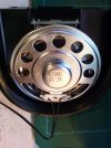
Then I fitted the flat speaker, which I kept in place with "black tack" which is a slightly stickier (and black) version of blutack. I fed the speaker cable under the weight and connected it to the Massoth S module, which I had already stuck to the front of the weight.

IMG_20200929_112616.jpg

Final bit of kit to be added was the keep alive capacitors, which fit neatly under the weight. Picture below shows all this gubbins. Luckily there is plenty of room inside this loco. I also added another driver figure, don't know why LGB/Maerklin are so mean as to only ship one with each steam locc.

IMG_20201004_161627.jpg

I made some changes to make the rear light and cab light separate from the front lighting, using A3 and A4, set to 5v. The A5 connection is used to control the stay alive so you don't have to disconnect it before you can do any programming. The A1 connection is used for the smoke generator (again 5v), and A6 for the firebox flicker (full voltage, just as well as you can't adjust the voltage on A5 or A6). A2 connection is not used.

The wiring into the XL decoder is now as follows:
  • smoke generator (black) and two of the front light leads (one from each light) into +22
  • black from "stay alive" into GND
  • the other two front light leads into LI-V
  • yellow from motor block into MOT+
  • white from motor block and white from Massoth S into GL+
  • brown from motor block and brown from Massoth S into GL-
  • green from motor block into MOT-
  • smoke generator (white) into A1
...and on the other end...
  • yellow from 5 way ribbon cable, red from "stay alive" and black from firebox flicker into +22 (the other one)
  • white (rear lights) from 5 way ribbon cable into A3
  • green (cab light) from 5 way ribbon cable into A4
  • white from "stay alive" int A5
  • black from firebox flicker into A6
Now for some more testing and CV tweaking. I'll post a list of the important CV settings when I'm done testing.
 

idlemarvel

Neither idle nor a marvel
13 Jul 2015
3,136
801
Ascot
Country
Mars
Best answers
0
Country flag
Thanks for the tip Greg but the firebox flicker is connected to the Massoth XL motor/lights decoder not directly to the track. I might have confused you with the reference to full voltage.
 

idlemarvel

Neither idle nor a marvel
13 Jul 2015
3,136
801
Ascot
Country
Mars
Best answers
0
Country flag
Enough tweaking. These are the CV settings I have used.

Motor settings (XL decoder)
I prefer not to use what Massoth call "load control" or back EMF. This is because I have no gradients and no long / heavy trains so it is really not needed, and the downside to load control is it makes locos "growl" at low speeds and to a greater or lesser extent "jumpy" or "jerky". Instead I increase the minimum speed CV2 until the loco moves, and set the maximum speed to scale speed 35 kmph (approximately) and the mid speed CV6 to half way. I also prefer more realistic acceleration and braking so the loco does not "stop on a sixpence". So in this case:
min speed CV2 = 28
mid speed CV6 = 78
max speed CV5 = 128
acceleration CV3 = 24
deceleration CV4 = 24

configuration CV29 = 2 (28 speed steps, no analog)
Massoth config CV49 = 0 (load control off, parallel commands only)

Light settings (XL decoder)
These are mainly dictated by the voltage required by the lights. In this case:
directional lighting CV50 = 5 (just under 5v)
aux 1+2 voltage CV53 = 8 (just over 5v, for conventional smoke generator)
aux 3+4 voltage CV112 = 5 (just under 5v, for cab light)
aux 5+6 voltage is fixed at track voltage (okay for firebox flicker)
For the power buffer ("stay alive" capacitors) there is a control lead in aux 5 so in addition:
buffer control CV118 = 31

Sound settings (S decoder)
In this loco the S decoder is connected to track power and not SUSI, so it is most convenient to have the same address as the motor decoder, as set in CV1 for 2 digit addresses. Also, because I have not installed a wheel sensor, I needed to used load control to speed up and slow down the chuffs. As a starting point, set CV1-6 and CV29 to be the same as for the motor decoder, except for CV4 (decelleration) which should be a lower number (quicker decelleration). I left it at the default of 3. The reason for this is when the loco slows down, you want the chuffs to stop before the loco stops.

To try and synchronise the chuff sounds with the wheels, there are four CVs to manipulate:
pulses per chuff CV195 = 1 (needed to make cylinder side noises)
pulse generation CV196 = 255 (load control rather then wheel sensor)
chuff max speed CV197 = 6 (arrived at by trial and error)
clock simulation CV198 = 192 (arrived at by trial and error)

Without a wheel sensor you can't get the chuffs to match perfectly but you can get quite close with these last two settings, if you set a linear speed curve. Strangely there is no SUSI CV equivalent to these in the CV900+ range so if you connect your Massoth S decoder via SUSI you have no control over the chuff rate, at least that is my experience, so you would definitely need a wheel sensor.

Finally the braking sound needed some adjustment. There are two CVs which affect when the sound of brakes is played automatically, and these are CV168 which is the speed (relative voltage) you have to reach before the brake sound is "enabled" and CV169 which is the speed at which the brake sound comes on. I set CV168 to 40 and CV169 to 30.

Most of the other CVs are to assign sounds to F keys, which are a matter of personal taste. The sounds provided vary according to the "sound project" loaded into the decoder.

The other useful CV to set on the S decoder is the "POM address". This is a dummy address that only responds to POM (programming on main) commands. This is useful so that you can change CV settings on the S decoder in POM mode without changing the ones on the XL at the same time. As I only have a few locos I set the POM address to be the loco address + 200.
 

Anglian

Registered
23 Jul 2018
1,540
602
75
Armagh
Best answers
0
Country flag
Hi. Thanks for this Dave. I've been following it carefully as I am converting a U class to take a Massoth L. I've worked out most of it, but I'm not sure where the grey and red wires for the multi-purpose socket attach to on the decoder.
Thanks for your time.
Trevor