idlemarvel
Neither idle nor a marvel
This model of steam locomotive #2 of the Spremberger Stadtbahn was produced in three different versions by LGB:
In 2001 - With decoder interface only.
In 2002 - With decoder interface and factory installed 55021 decoder.
In 2003 - With installed 'on-board' decoder.
Mine is a "2001" model (date stamped 01/01/01!). To open her up, there are only two screws, although they are awkward to get to because of the running gear. Then undo the clip at the front under the smokebox door and it "flips back". This is easier if you remove the clip on brake pipes first, front and rear.
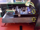
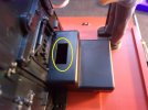
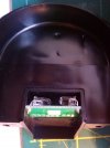
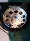
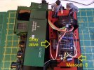
EDIT: pictures added below. First shows location of screws, second the front clip and third the hinge point.
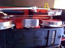
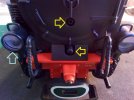
Note: the screw marked with the ywllo arrow holds the clip in place, I plan to remove these as they are hardly prototypical! Also I have added the headlight rims (blue arrow).
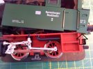
Once the top is off the next tricky bit is to remove the weight. You think there are just two screws but there is a hidden screw underneath fixing the circuit board to the bottom of the weight, so you have to unscrew the circuit board as well.
Inside there is an old fashioned circuit board (see picture). There are four black wires soldered to it for the front lights (5v bulbs), two pins for the black and white cables for the smoke generator (5v), and a 5-pin socket, with white, green, yellow, gray and red ribbon cable. The red and gray go to the multi-purpose socket at the rear of the loco, the white is for the rear lights, green for the cab light and yellow is the common. The lights are all 5v bulbs.
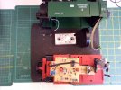
There is also a 6-pin decoder socket so with an old 55021 decoder and a 6-pin interface cable you could quickly install a decoder which was of course the intention at the time. I happened to have a spare XL decoder so it was easier just to strip out the old circuit board and wire up the decoder directly. I unsoldered the front lights and removed the board and associated wiring. Then I attached yellow, white, brown and green cables to the motor block pins (see picture), replaced the weight, ran the cables underneath the weight and attached them to the XL decoder. I covered the top of the weight with insulating tape and screwed the decoder onto the weight (see picture). Time to test the motor. Always best to test on programming track first to make sure there are no short circuits.
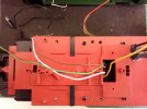
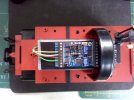
Then I attached the light and smoke generator wires as follows:
smoke generator (black) and two of the front light leads (one from each light) into +22
In 2001 - With decoder interface only.
In 2002 - With decoder interface and factory installed 55021 decoder.
In 2003 - With installed 'on-board' decoder.
Mine is a "2001" model (date stamped 01/01/01!). To open her up, there are only two screws, although they are awkward to get to because of the running gear. Then undo the clip at the front under the smokebox door and it "flips back". This is easier if you remove the clip on brake pipes first, front and rear.
EDIT: pictures added below. First shows location of screws, second the front clip and third the hinge point.


Note: the screw marked with the ywllo arrow holds the clip in place, I plan to remove these as they are hardly prototypical! Also I have added the headlight rims (blue arrow).

Once the top is off the next tricky bit is to remove the weight. You think there are just two screws but there is a hidden screw underneath fixing the circuit board to the bottom of the weight, so you have to unscrew the circuit board as well.
Inside there is an old fashioned circuit board (see picture). There are four black wires soldered to it for the front lights (5v bulbs), two pins for the black and white cables for the smoke generator (5v), and a 5-pin socket, with white, green, yellow, gray and red ribbon cable. The red and gray go to the multi-purpose socket at the rear of the loco, the white is for the rear lights, green for the cab light and yellow is the common. The lights are all 5v bulbs.

There is also a 6-pin decoder socket so with an old 55021 decoder and a 6-pin interface cable you could quickly install a decoder which was of course the intention at the time. I happened to have a spare XL decoder so it was easier just to strip out the old circuit board and wire up the decoder directly. I unsoldered the front lights and removed the board and associated wiring. Then I attached yellow, white, brown and green cables to the motor block pins (see picture), replaced the weight, ran the cables underneath the weight and attached them to the XL decoder. I covered the top of the weight with insulating tape and screwed the decoder onto the weight (see picture). Time to test the motor. Always best to test on programming track first to make sure there are no short circuits.


Then I attached the light and smoke generator wires as follows:
smoke generator (black) and two of the front light leads (one from each light) into +22
- the other two front light leads into LI-V
- yellow from motor block into MOT+
- white from motor block into GL+
- brown from motor block into GL-
- green from motor block into MOT-
- white from 5 way ribbon cable into LI-H
- smoke generator (white) into A1
- yellow from 5 way ribbon cable into +22 (the other one)
- green from 5 way ribbon cable into LI-I
Last edited:


