Electric Points Control (LGB/Piko)

Gizzy

A gentleman, a scholar, and a railway modeller....
Country flag
I've often heard forum folk say that the LGB/Piko boxes for switching electrically operated points are quite expensive.

I have often posted here about a much cheaper alternative from Gaugemaster, but it seems that it is still not known about.


I used these myself when I was an analogue operator. Instructions are provided, and they can be easily fitted inside a suitable enclosure.

I commend these to the forum....
 
cheers Gizzy, from a facination point of view as a layman, what the diodes actually doing in this pack, when the switch is activated
 
Last edited:
Diodes rectify alternating current AC to direct current DC.

The point motors work on DC which is switched to give the direction for the point blades....
 
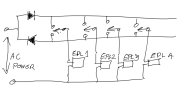
I made my own panel. just get SPDT center off momentary switches. One side of the switch connects to a diode in series to the supply, the other side connects reversed to the other side. Now run a wire between the outer sides of the switches. center of the switch goes each EPL drive independently as well as the other power supply lead goes to the other EPL connection. SO, only 2 diodes are needed as they feed all the switches. Plus one can individually place the switches on a marked up track diagram!!
 
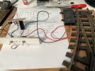
The bits turned up today and so I had a quick go at trying out a centre off momentary switch (DPDTCO in this case). 15V DC input to 6800µF capacitor, no diodes required! Performance is impressive and probably the equal of the LGB EPL Booster I currently use. If I go ahead with next year's extension, centre off switches mounted in a diagram panel will be the way to go.
point_control_experiment.jpg
 
Last edited:
I made my own panel. just get SPDT center off momentary switches. One side of the switch connects to a diode in series to the supply, the other side connects reversed to the other side. Now run a wire between the outer sides of the switches. center of the switch goes each EPL drive independently as well as the other power supply lead goes to the other EPL connection. SO, only 2 diodes are needed as they feed all the switches. Plus one can individually place the switches on a marked up track diagram!!

i don't understand that.
i always thought, the advantage of the EPL system was to save on cables by using more diodes.
 
So effectively creating a DC bus (well2 actually) that provides drive for the point motors?

This bloke has an interesting way of changing LGB points using a 12V battery to supply the DC and loops on the switches so that only 1 positive line is needed.
He is a bit long winded but gets the message across

He also uses a solar panel to keep the battery charged similar to what I do to get 12V out in the garden.
 
Back
Top Bottom