Converting Lgb 23881 back to DC

Tumble99

Registered
24 Aug 2020
9
3
31
Australia
Best answers
0
Country flag
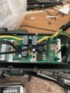
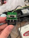
Hi all, I recently purchased an LGB 23881 Uintah mallet, I run DC track power through the RCS Titan trackside. Anyway, the locomotive had a Massoth eMotion ME 8210088 Decoder and sound card installed, which will run on DC at a restricted speed.

I have tried disconnecting the Decoder and the locomotive did not work at all.

I am wondering 1. does anyone have any photos of the original electronics for the 23881 mallet as I have been unable to find any to see if anything else was adjusted?
2. if someone has a massoth DCC controller can the card be set for DC track power.

Thanks for your help in advance
 

PhilP

G Scale, 7/8th's, Electronics
5 Jun 2013
33,597
3,525
Nottingham
Best answers
0
Country flag
How about posting a picture of what you have?

If the board in your loco has a set of DIP switches, did you switch then back on? - The first 4, are for track and motor..

PhilP
 

Tumble99

Registered
24 Aug 2020
9
3
31
Australia
Best answers
0
Country flag
Hi Phillip, thank you for your reply. Are you referring to the switch in the firebox? that was set to 4 attached below is the mainboard for the loco with the decoder removed.
 

Attachments

  • LGB 23881.jpg
    LGB 23881.jpg
    10 KB · Views: 0
  • LGB 23881 firebox.jpg
    LGB 23881 firebox.jpg
    8.8 KB · Views: 0

phils2um

Phil S
11 Sep 2015
1,522
423
Ann Arbor, Michigan
Country
United-States
Best answers
0
Country flag
It looks like the original electronics were removed from your first pic. I'm not familiar with the Titan RCS system. If it is otherwise compatible, I suggest your best move may be to find someone who can reprogram the Massoth decoder maximum analog speed CV and leave the decoder and sound card in place.
 

dunnyrail

DOGS, Garden Railways, Steam Trains, Jive Dancing,
Staff member
GSC Moderator
25 Oct 2009
26,209
4,998
75
St.Neots Cambridgeshire UK
Best answers
0
Country flag
Hm that looks very much like an original DCC board to me. Conversion back to analogue would mean taking that out and connecting the track wires to the motors. Not the simplest of jobs if you are unfamiliar with model electronics. Also this would disable lighting and the smoke generator without additional wiring.

From those grey plugs the following are the routes taken
Yellow Green to Motor
Brown and White to track

You would thus need both sets coupled to get full pickup and both bogies with motors connected. It is also possible that the wires may be reversed to each source thus you would need to check out each bogie set for running as you connect the wires. This is because the bogies are located as mirror images at each end and those differences would be sorted in the circuit board. A terminal strip is the best way to connect the wires thus allowing changes.
 

muns

Well-Known Member
Staff member
GSC Moderator
24 Oct 2009
5,718
130
Southampton, U.K.
www.gardenrailoutlet.co.uk
Best answers
0
Country flag
Ok so the XLS decoder was connected using a 10pin interface cable?

What you need to restore this to DC power is a jumper that bridges the 10pin interface connector and the 3pin connector directly allongside it.

Unfortunately I cannot tell you which pins need to connected together.
 
Last edited:

PhilP

G Scale, 7/8th's, Electronics
5 Jun 2013
33,597
3,525
Nottingham
Best answers
0
Country flag
I concur with Phil (in post #4).. You do not appear to have the original circuit board (for an analogue loco) to connect things to.

The decoder electronics, will not 'wake-up' until there is 5-6V available, so the loco will seem sluggish, compared with a full analogue loco.

In answer to your second question (in your first post) someone with DCC equipment, and a little knowledge of Massoth CV's, would be able to set up the decoder to your requirements.

As an aside, to others:
The RCS Titan trackside system, is similar to the Revolution Train Engineer..
A radio control system, controlling power to the track.

PhilP
 
8 Mar 2014
7,806
972
San Diego
Country
Armenia
www.elmassian.com
Best answers
0
Country flag
Why do you guys (Phil S and Phil P) say that is not a stock board?

Here's a picture from another loco of the same type:

thumbnail_img_4538-jpg.562768.jpg

Same components and connectors on the left side ... (yes yes, the main board is wired to something else in this picture, but the board shown by the OP surely looks stock)

Greg
 

PhilP

G Scale, 7/8th's, Electronics
5 Jun 2013
33,597
3,525
Nottingham
Best answers
0
Country flag
Why do you guys (Phil S and Phil P) say that is not a stock board?

Here's a picture from another loco of the same type:

View attachment 296938

Same components and connectors on the left side ... (yes yes, the main board is wired to something else in this picture, but the board shown by the OP surely looks stock)

Greg
Greg,
That board allows you to plug a number of the 'standard' LGB connectors onto it, and then use the Massoth 10-pin interface cable, to wire into a Massoth XLS (or other) decoder..
Without this, you have to cut the original connectors off, solder track and motor leads (from the two motor blocks) and possibly strip-back some of the lighting connectors.

This makes fitting a decoder a lot easier, if you are not happy weilding a soldering iron..

An original board, would have had a Bank of dip switches, and pins on the board, to allow the connection between track-power and motor(s) to be isolated, and fed 'out and back' to a decoder..
Massoth used to supply a 10-pin cable, and sets of leads with the correct connectors for either these pins, or directly to the pins on the motor block.

PhilP
 

The Shed

Citizen of the Republic of the North East.
8 Mar 2020
1,072
238
Darlington, County Durham.
Country
England
Best answers
0
LGB Backplate.JPG
 

phils2um

Phil S
11 Sep 2015
1,522
423
Ann Arbor, Michigan
Country
United-States
Best answers
0
Country flag
Hi Greg,

After looking again, I do think this is the original 10 pin decoder interface board complete with voltage regulation for lights, etc. Mark has alluded to this in post #6. The decoder and sound card are not shown. I don't have any locos with this 10 pin generation of interface board so did not recognize it. All mine are before (6 pin + separate motor and track pins and dip switches) or after (LGB On-board decoders). While I was typing this The Shed has provided the answer Mark could not on how the "Blanking Plug" is wired.

I still think I would leave the decoder and sound card installed and get the decoder analog operation CVs changed to increase the max speed.
 
Last edited:
8 Mar 2014
7,806
972
San Diego
Country
Armenia
www.elmassian.com
Best answers
0
Country flag
I agree with you, I believe the system is workable, and would try this first before ripping things out.

Also, perhaps the OP might not be giving enough voltage, we should check that even before changing CVs

The RCS Titan will handle up to 24 volts input, but the OP should be aware that a few volts are "lost" in the Titan, so assume 2 volts or so lost from the power supply input to the track output.

now, in addition, you lose 2-3 volts through the decoder, since it takes the "DC" on the tracks and uses it to drive the decoder output transistors in pwm to the motor.

So, we need the input voltage to the RCS throttle. It's actually very likely that the decoder is already programmed not to limit top speed, which is the default.

Greg
 

Tumble99

Registered
24 Aug 2020
9
3
31
Australia
Best answers
0
Country flag
A little update, thank you all for the replies, thank you to The Shed for the blank plug, I wired up my own temporary Blank plug with Dupont cables, which worked, however, the heat generated caused the plugs to melt together. Unfortunately, the speed was still similar which is interesting. The decoder is still insitu atm soo after sport today I will get back to it.


Thanks, everyone once again, If anyone has massoth in Adelaide Let me know.
 

Dan

Registered
28 Jan 2010
660
52
Eastern MA, USA
Best answers
0
Country flag
The board shown in the first picture is definitely the original LGB DC only board that needed the special 10 pin plug to operate. LGB DCC boards looked similiar but had 4 of the 4 pin connectors in the middle as the forth one was usually red and had the SUSI bus info for the LGB sound unit. When going to DCC one had to remove the jumper plug and use the LGB 55027 DCC decoder which did NOT give you sound or the susi connection.

Also note that my 23881 LGB info shows this engine having the 55020 single motor decoder and the 55030 for the 2nd motor block. Sometimes LGB upgrades engines but does not update any diagrams/info.
 

LGB333

Active Member
TRADER
15 Feb 2015
689
43
McLean Virginia
www.olddominionrailways.com
Best answers
0
Country flag
The factory configuration of the LGB 23881 has a circuit board with a 10-pole DCC Interface and the engine ran on DC analog power. So, in theory, unless someone jury-rigged a modification to the electronics, you should be able to disconnect the DCC decoder and switch the dip-switches back to the On position. The factory setting should then be restored to DC analog power.

Instead of disconnecting the XLS decoder connected to the circuit board, the XLS could be adjusted to improve the DC voltage output to the motors, but the user apparently doesn't have a DDC system to read and write the CVs to do that.
 
8 Mar 2014
7,806
972
San Diego
Country
Armenia
www.elmassian.com
Best answers
0
Country flag
Folks, are we really doing out best here?

First, we are finally in agreement it is the stock board.

Are there really dip switches on it? Can we all agree that with the 10 pin socket (which Shed so kindly illustrated) there are no dip switches?

Now, to the helpful part... Tom, when you say "the XLS could be adjusted to improve DC voltage output to motors". That is false.
  1. how do you KNOW that CV 5 is not set to max already?
  2. we need to know if the problem is indeed "top speed" as implied, or is it that it runs slower next to a non-decoder equipped loco?

In either case, perhaps the only solution that will please the OP is removing the decoder, since a decoder-equipped loco will ALWAYS run slower than the SAME loco with the decoder out. (the voltage drop from the decoder input bridge and the output transistors)


So, maybe we can better help the OP.

From his post #13, my bet is his DC supply is low on volts or amps or both.

So Tumble99, can you please indicate the DC power unit (make and model) you are testing with?

Greg
 

LGB333

Active Member
TRADER
15 Feb 2015
689
43
McLean Virginia
www.olddominionrailways.com
Best answers
0
Country flag
Folks, are we really doing out best here?

First, we are finally in agreement it is the stock board.

Are there really dip switches on it? Can we all agree that with the 10 pin socket (which Shed so kindly illustrated) there are no dip switches?

Now, to the helpful part... Tom, when you say "the XLS could be adjusted to improve DC voltage output to motors". That is false.
  1. how do you KNOW that CV 5 is not set to max already?
  2. we need to know if the problem is indeed "top speed" as implied, or is it that it runs slower next to a non-decoder equipped loco?

In either case, perhaps the only solution that will please the OP is removing the decoder, since a decoder-equipped loco will ALWAYS run slower than the SAME loco with the decoder out. (the voltage drop from the decoder input bridge and the output transistors)


So, maybe we can better help the OP.

From his post #13, my bet is his DC supply is low on volts or amps or both.

So Tumble99, can you please indicate the DC power unit (make and model) you are testing with?

Greg
Greg - Your statement: "Now, to the helpful part... Tom, when you say "the XLS could be adjusted to improve DC voltage output to motors". That is false." Okay, I think you know what I meant, that the XLS has the capability for making adjustments to the DC voltage output to the motors. So, since we both don't know what the settings are, the motor operation might have the capability to be improve or maybe not be improved.
 
8 Mar 2014
7,806
972
San Diego
Country
Armenia
www.elmassian.com
Best answers
0
Country flag
Right, but MIGHT, not CAN. Since he says removing the decoder did not make much/and difference, from post #13 we can now assume that it's not CV5 in the decoder that was limiting top speed, right?

What I am saying is: being helpful is not going back and forth on theories that have the answer right in the thread itself.

I try to put myself in the OP's shoes, and it's got to be frustrating already.... sorry to critique your post, but you do indeed present yourself as a professional installer and dealer.


Greg
 

PhilP

G Scale, 7/8th's, Electronics
5 Jun 2013
33,597
3,525
Nottingham
Best answers
0
Country flag
I know the OP said he used DuPont jumpers..
But the fact 'things melted' is slightly worrying?

I you try to solder to header-pins in free-air, then it is quite easy to melt (soften) the plastic, and lose the pin alignment..
If you plug the pins in, they are held in alignment, and the sockets take some of the heat, so less chance of problems.

A couple of Buhler motors (if running as they should) should not take enough current to melt wiring.
Perhaps the smoke unit is also running?

PhilP