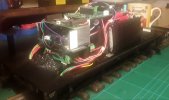
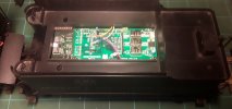
Converting Bachmann 2 x K-27 & Climax to battery power with Sierra sound

maxi-model

UK/US/ROW steam narrow gauge railways 1:1
27 Oct 2009
5,673
661
Bucks/Oxon/Northants area
Best answers
0
Country flag
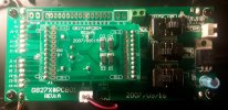
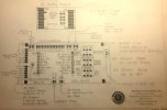
Ok, rather than dredging up the old thread, where I made my initial enquiries, I have started a new one here to cover the actual installation of a suite of components bought from RCS. A swift and reliable supplier and a damn decent one to deal with. There are a couple of non orthodox elements - the use of old Sierra Soundtraxx sound cards and the use of the onboard chuff sensors supplied with these locos. In the case of the Sierras an RCS SSI-9 device has been included to get round the PWM issue and a neat little fix has been supplied to get round the "chuff inversion" issue with the K-27 chuff sensors. Now here is my problem - while I am confident of being able to wire it up as per the supplied diagram, attached, I am a little confused as to instructions I have been given as to where the voltage/battery inputs should go in to the locos themselves. It seems logical that the output from the ESC should go in at the points marked +MOTOR- on the top left of the PCB. It should then follow, to my mind, that fly leads from the battery should input into the screw terminal block, right of the legend PICK UP marked +BATT-. However my instructions say that only the ESC output should be connected to this last mentioned terminal labeled for battery input and nothing else. I include images of the PCB with/without dummy DC PCB in place so all the legends are visible. I also have included Bachmann's own schematics and RCS's installation sheet for further clarity. What is the right way to do this ? The supplier is presently unavailable to answer my queries. Note that there are no ground wires used in the Sierra trigger circuits.

Loco PCB without dummy DC PCB
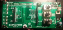
20210215_191050.jpg
Loco PCB with dummy in place
20210215_190751.jpg
RCS full installation sheet, specific to installs using the Sierra card and SSI-9. I am using the supplied Cobra ESC
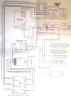
20210215_130459.jpg
Bachmann PCB schematic
20210210_192930.jpg

Just a little P.S.The component set supplied also includes one of their neat battery PnP's, to replace the dummy DC PCB's. It apparently allows the full functionality of the PCB to be employed. One problem RCS have not updated their Install instructions to demonstrate its incorporation in one involving a Sierra card and SSI-9. I do not intend to use it unless there is a very good reason to. Here is an image of how it would look if installed. I get the motor + & - inputs and I can understand the wires intended for connecting front and rear lights to marked outputs on the ESC for directional operation. It's the 2 middle ones, black and blue that go into the ground and decoder pins that have me mystified.
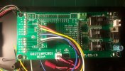
20210215_194657.jpg

Sorry if this is all a bit dense, in both meanings but I do not have the confidence to install with the apparent conflicts and omissions I am presented with. Self inflicted in all probability. Max
 
8 Mar 2014
7,806
972
San Diego
Country
Armenia
www.elmassian.com
Best answers
0
Country flag
Can you present the instructions that say:
However my instructions say that only the ESC output should be connected to this last mentioned terminal labeled for battery input and nothing else.

That information is not shown. (and it is wrong, probably for some other loco or situation)

Normally when you feed the ESC output into the power input, it's to avoid re-wiring lights or other items. For example, my quick and dirty method to DCC USA Trains diesels connect the motor outputs directly to the entire main board, thus lighting the lights but they will not be constant voltage.

Greg
 

PhilP

G Scale, 7/8th's, Electronics
5 Jun 2013
33,561
3,521
Nottingham
Best answers
0
Country flag
First point :
If being done as a 'simple' install, you are just replacing track DC in, with the output of the ESC, so should only connect the output from the ESC Once.

Regarding the little break-out board:
This is just a convenient way to get into the loco wiring..
The board could also be used for a DCC installation. In this case, the 'decoder +' would be the common connection for the lighting, and the 'decoder -' would give a negative reference, possibly for the original chuff sensors?

So I do not believe you need to connect these two wires.

I would urge a little caution, and suggest you wait for clarification / confirmation from Tony.

PhilP.

<edit> Greg and I typing at same time..
 

Tony Walsham

Manufacturer of RCS Radio Control.
25 Oct 2009
2,221
50
Casino, NSW
Best answers
0
Country flag
Hello Max
Do not make use of any Stock Bachmann K27 or other items show
Use only the instructions supplied with the #RCS-Battery-PnP kit.

The battery supply is then fed into the BIK-u3a kit NOT the Bachmann socket pcb. All other wiring is taken into account with the supplied instructions.
The only addition required is the chuff signal inverter as shown with the instructions previous;y sent.
Bachmann chuff signal inverter.
Do not make use of any Stock Bachmann K27 or other items shown, such as the old design adaptor plate shown.
I should be home this coming weekend when I can arrange verbal communication.
 
Last edited:

maxi-model

UK/US/ROW steam narrow gauge railways 1:1
27 Oct 2009
5,673
661
Bucks/Oxon/Northants area
Best answers
0
Country flag
Thanks for all your inputs. Glad to see you are back in circulation Tony, I was getting worried there.

"Use only the instructions supplied with the #RCS-Battery-PnP kit."

The problem here Tony is the instructions supplied to me with the Battery-PNP kits, and those available via the link, stop short of showing this part incorporated in an installation with a Sierra & SSI-9. The RX & ESC variations I can figure out. The last sheet, stapled in, with this part's documentation as supplied is just the regular SSI-9 install sheet, which has no reference to the Battery-PNP kit incorporation in it. Also the 2 "centre" wires are variously described black and blue or black and red. As shown their pins go into holes marked GND & Decoder on the Bachmann PCB, not the self evident function pairings of the the other 4 assigned pins - motor & lights.

Where the Battery-PNP kit's attendant leads go I am having to guess - the red & black ones with the JCT attached on the end - the ESC ? The white & yellow ones emanating from the Light R and Light F pins I assume go to the ESC's dedicated terminals for F&R directional lights (as a point of note my K-27's like others do not have a rear light fitted. I assume that is a redundant generic thing) The centre pair, either, Black & Blue or Red & Black - direct to battery or redundant ? These last two leads assignation seem to change dependent on the type of installation. With no actual schematic showing the Battery PNP kit with the Sieara and SSI-9 incorporated I am left in limbo here.

Your statement Tony - "Do not make use of any Stock Bachmann K27 or other items show" - Which stock items are you referring to, the DC dummy PCB or more ?

You can perhaps see the various sources of my confusion now.

The real issue is that my relationship with electronic stuff is very much like a dyslexic to words. Yes, I can follow a schematic, at least where the wires go and so long as there are no fancy symbols. But it has to be explicit, with no room for conjecture. That is the situation I have now - I do not have a schematic that is explicitly for an installation using the battery-PNP kit in conjunction with a Sierra Soundtraxx card and the attendant SSI-9 to sort out the PWM issue. I need a "join it by numbers" guide, no ifs or buts. I have an reluctance for these reasons, and resultant inability, to improvise where electronics is concerned.

I shall await further instructions. Max
 

maxi-model

UK/US/ROW steam narrow gauge railways 1:1
27 Oct 2009
5,673
661
Bucks/Oxon/Northants area
Best answers
0
Country flag
The penny has finally dropped on the RCS Battery-PNP kit. It's a very neat simple solution to adding battery and rc to a Bachmann loco fitted with the PNP PCB. Max.
 

Tony Walsham

Manufacturer of RCS Radio Control.
25 Oct 2009
2,221
50
Casino, NSW
Best answers
0
Country flag
Hello Max.
I am far from recovered. I have Lyphoma that is apparently quite aggressive.
It will be some weeks before I can function properly
 

PhilP

G Scale, 7/8th's, Electronics
5 Jun 2013
33,561
3,521
Nottingham
Best answers
0
Country flag
Tony sent me a PM, asking if I would help Max with this..
I have been sent the schematics and instructions, and will review them with Max..

Once Max is sorted, he will update the thread.

This should allow Tony to concentrate on getting fit again.

PhilP.
 

maxi-model

UK/US/ROW steam narrow gauge railways 1:1
27 Oct 2009
5,673
661
Bucks/Oxon/Northants area
Best answers
0
Country flag
I have to offer my sincearest thanks to Tony, despite his situation, in directing PhilP to come to my aid and at such short notice.. All the best to you Tony and stay strong. Looking forward to seeing you up and about and back at the helm soon..You can't beat this forum for the help and depth of support that is here. Max
 

maxi-model

UK/US/ROW steam narrow gauge railways 1:1
27 Oct 2009
5,673
661
Bucks/Oxon/Northants area
Best answers
0
Country flag
Success ! Thanks the Tony's wonderful kit and PhilP, of this parish and RC Trains fame, ministrations and patience. I bring you a video of the now all singing and dancing Bachman K-27 for what it is worth. Just got to tidy up all the packaging of the cards, tweak the Sierra's sound settings, close it all up and take it for a proper run. Two more to do this way and another 8 to follow.


This installation uses RCS's little gizmo, the SSI-9, to overcome issues of using old Sierra cards with modern PWM outputting ESC's. Also a rather neat attachment that replaces the Bachmann dummy DC PCB with their RCS's own PnP input for both motor power from the ESC, battery input to provide power to the classification lights, head light, cab light and firebox flicker, while the loco is at rest. It also does the directional lighting power inputs from the ESC.

Note - The K-27's lighting circuit was switched off during the test, it does work. The bell and "grade crossing" whistle sound sequences are both voltage and trigger operated on the Sierra. I will be dialling out their voltage operation, relying on rc trigger operation alone. These can be set to be latched or for momentary operation. The chuff sounds are activated by the K-27's own trigger. This was made possible by a little device that Tony supplied that bridges positions on the Bachmann PCB. In this installation. Neither the Sierra's common ground on its sound trigger side nor it's normal 3 pin mini plug and DPDT switch arrangement is used for power here. The wiring schematic, followed, minus the PnP board, is posted earlier in the thread.

20210306_194434.jpg

Alls well that ends well. A bit of a learning curve there. I feel a bit more confident about these things now. Thanks for every bodies inputs. I hope things are going in the right direction for you Tony, all the best. Max
 

dunnyrail

DOGS, Garden Railways, Steam Trains, Jive Dancing,
Staff member
GSC Moderator
25 Oct 2009
26,164
4,989
75
St.Neots Cambridgeshire UK
Best answers
0
Country flag
Success ! Thanks the Tony's wonderful kit and PhilP, of this parish and RC Trains fame, ministrations and patience. I bring you a video of the now all singing and dancing Bachman K-27 for what it is worth. Just got to tidy up all the packaging of the cards, tweak the Sierra's sound settings, close it all up and take it for a proper run. Two more to do this way and another 8 to follow.


This installation uses RCS's little gizmo, the SSI-9, to overcome issues of using old Sierra cards with modern PWM outputting ESC's. Also a rather neat attachment that replaces the Bachmann dummy DC PCB with their RCS's own PnP input for both motor power from the ESC, battery input to provide power to the classification lights, head light, cab light and firebox flicker, while the loco is at rest. It also does the directional lighting power inputs from the ESC.

Note - The K-27's lighting circuit was switched off during the test, it does work. The bell and "grade crossing" whistle sound sequences are both voltage and trigger operated on the Sierra. I will be dialling out their voltage operation, relying on rc trigger operation alone. These can be set to be latched or for momentary operation. The chuff sounds are activated by the K-27's own trigger. This was made possible by a little device that Tony supplied that bridges positions on the Bachmann PCB. In this installation. Neither the Sierra's common ground on its sound trigger side nor it's normal 3 pin mini plug and DPDT switch arrangement is used for power here. The wiring schematic, followed, minus the PnP board, is posted earlier in the thread.

View attachment 281900

Alls well that ends well. A bit of a learning curve there. I feel a bit more confident about these things now. Thanks for every bodies inputs. I hope things are going in the right direction for you Tony, all the best. Max
Certainly sounds the biscuit to me.
 

soupsandwich

Registered
2 Feb 2021
6
0
66
Leicestershire
Best answers
0
Country flag
Hi Max,

That looks like a great success and quite inspirational. Reading the info of how you did it is very complex and a bit over my head. I have 2 locos to 'batteryfy' both Bachmanns' and to me it looks somewhat daunting. What first step would you advise ? I have a very basic knowledge of electrical circuitry, mainly through adding a couple of ring mains to my house years ago but that is pretty basic comparatively. Is it as simple as just following instructions that come with the conversion kits ? There seem to be sooo many different configurations of 'chuff' sounds, lighting, backwards/forwards, soundcards etc. If you have a moment I'd appreciate a couple of pointers as to where to start ?

Thanks

Ian, (soupsandwich)
 

maxi-model

UK/US/ROW steam narrow gauge railways 1:1
27 Oct 2009
5,673
661
Bucks/Oxon/Northants area
Best answers
0
Country flag
Hello Ian. I am probably the very last person to ask for advice . However what has got me through this, and a couple of other installations, has been posting on this forum and getting some very good advise and practical support, from members who have the expertise. Post a topic outlining what you want to achieve and the replies will flow. Trust me

There are one or two very good traders I have used who can provide a good selection of well matched state of the art, as well as old school, products and can act as a "one stop shop" to provide a complete suite of components for a final reliable system. The ones I have used are - Fosworks, RCS, Brian Jones & RC Trains. There are others. The mentioned suppliers are all very good at assessing customer's individual needs and providing the systems that meet them. They all have a depth of knowledge needed when dealing with the requirements of large scale locos used outdoors. They all will provide ample support once your chosen options have been supplied.

The products I have bought so far, from those mentioned suppliers, have always come with clear instructions and wiring diagrams. Although I have sometimes found I need to ask for additional clarification, usually because I am trying to integrate something that was not originally envisage as part of a regular installation. That and my own innate stupidity.

If all else fails most suppliers offer an installation service or can direct you to agents who can do this work. To be honest the balance of my "fleet" will in all probability be done by a supplier - some need a lot of wire cutting and others bits spliced in. The Bachmann K-27 featured in this thread, while it may look complicated, is quite simple - once you understand (or should I say be told) that you just need to place 7 wires in the right place (and 6 of those are pre-configured on their own card by the supplier) on that big PCB on top and "hey presto !" it all works. It's just me that makes it look complicated, that and integrating an old school sound card that has special needs.

If you can wire a ring main, so you don't burn the house down, then you won't have much problem doing a loco battery (+ rc/sound). Miswiring a loco won't have such a disastrous outcome as misfiring a house. Make the post and make a call. All the best. Max
 

JimmyB

Now retired - trains and fishing
23 Feb 2018
6,946
921
69
Weston-super-Mare
www.tumble-down-falls.co.uk
Best answers
0
Country flag
If you can wire a ring main, so you don't burn the house down, then you won't have much problem doing a loco battery (+ rc/sound). Miswiring a loco won't have such a disastrous outcome as misfiring a house. Make the post and make a call. All the best. Max
But remember to wire a ring main you need to be certified, or have a Part P inspection certificate :)
 

dunnyrail

DOGS, Garden Railways, Steam Trains, Jive Dancing,
Staff member
GSC Moderator
25 Oct 2009
26,164
4,989
75
St.Neots Cambridgeshire UK
Best answers
0
Country flag
But remember to wire a ring main you need to be certified, or have a Part P inspection certificate :)
These days yes but when I did my own back in 1987 anything went.
Hi Max,

That looks like a great success and quite inspirational. Reading the info of how you did it is very complex and a bit over my head. I have 2 locos to 'batteryfy' both Bachmanns' and to me it looks somewhat daunting. What first step would you advise ? I have a very basic knowledge of electrical circuitry, mainly through adding a couple of ring mains to my house years ago but that is pretty basic comparatively. Is it as simple as just following instructions that come with the conversion kits ? There seem to be sooo many different configurations of 'chuff' sounds, lighting, backwards/forwards, soundcards etc. If you have a moment I'd appreciate a couple of pointers as to where to start ?

Thanks

Ian, (soupsandwich)
As for your query Ian, pretty well every conversion is different even sometimes with the same loco. Depending on what you are doing it is sometimes worthwhile ditching the exsiting board and going from complete scratch ekectrical wise. But it depends on the loco, as I said all can de different. My thoughts would be go for something simple to start with so that you get a feel of what you are doing. Just an LGB Chassis block with a battery setup in an open wagon behind will give you a start. What you have used will not be wasted and can be incorporated into something else. This link will show you how I did a test kit for a Battery DCC System that I reviewed.

I and others have done lots of battery conversions, well worth a trawl through the Battery Thread. I must also point you to the GE_Rik blog well worth a look. He has it linked on all of his posts.
 

maxi-model

UK/US/ROW steam narrow gauge railways 1:1
27 Oct 2009
5,673
661
Bucks/Oxon/Northants area
Best answers
0
Country flag
But remember to wire a ring main you need to be certified, or have a Part P inspection certificate :)
I know Jimmy. I had my whole house recently rewired. Some of the old wiring was cloth covered twisted pairs with brown Bakelite 13 amp sockets dotted around the place. We only have to be plain certified to rewire a loco :D Getting the part P was delayed by the first Corona virus lock down. Having said that it did not stop the sparks, doing the job, accidentally putting a metal cutting disk through one of the central heating pipes. That was fun. Just as well he had a plumber mate near at hand to come around and staunch the flow of water from upstairs to downstairs. Many a thumb was employed. Max
 

Rhinochugger

Retired Oik
27 Oct 2009
36,710
4,240
North West Norfolk
Best answers
0
Country flag
These days yes but when I did my own back in 1987 anything went.
.................... up in smoke :eek::eek:

Actually, what brought about the change was when the wife of somebody important in a Kensington flat touched the stainless steel splashback behind the kitchen units and was killed. I seem to recall that it was in the days when Two Jags was DPM and in order to give him something to do, they put his office in charge of Building Regs :nod::nod:
 

dunnyrail

DOGS, Garden Railways, Steam Trains, Jive Dancing,
Staff member
GSC Moderator
25 Oct 2009
26,164
4,989
75
St.Neots Cambridgeshire UK
Best answers
0
Country flag
.................... up in smoke :eek::eek:

Actually, what brought about the change was when the wife of somebody important in a Kensington flat touched the stainless steel splashback behind the kitchen units and was killed. I seem to recall that it was in the days when Two Jags was DPM and in order to give him something to do, they put his office in charge of Building Regs :nod::nod:
Presumably if it had been the wife of someone that was not important 2 jags could have got on with his transport projects earlier.
 

Rhinochugger

Retired Oik
27 Oct 2009
36,710
4,240
North West Norfolk
Best answers
0
Country flag
Presumably if it had been the wife of someone that was not important 2 jags could have got on with his transport projects earlier.
The Blair government years placed the most statutes of any government, and the Bulding Regs changes were coming thick and fast.

However, as we have learned from the Grenfell enquiry, the process for ensuring that the regs were fit for purpose has been thrown into doubt.
 

maxi-model

UK/US/ROW steam narrow gauge railways 1:1
27 Oct 2009
5,673
661
Bucks/Oxon/Northants area
Best answers
0
Country flag
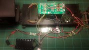
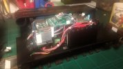
Final bit getting all the bits packaged up neatly in the tender - On the ground floor, the ESC, the PWM to linear converter (SSI-9) for the Sierra, battery packs and Visaton FRS 7 speaker. Mezzanine, the RX and sound triggers. Penthouse suite, the Sierra sound card and the Bachmann's own PCB with the RCS PnP card. The mezzanine and Sierra can be lifted out. All that needs to be accessible is up top under the coal load. The main switch and charger socket are under the water tank filler flap.

Just got to tweak the Sierra, to get it the way I like, then it's out for a run on the West Well. Max

20210309_212420.jpg20210309_212634.jpg20210309_214629.jpg