maxi-model
UK/US/ROW steam narrow gauge railways 1:1
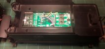
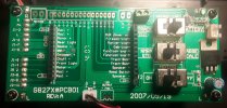
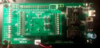
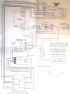
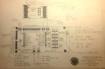
Ok, rather than dredging up the old thread, where I made my initial enquiries, I have started a new one here to cover the actual installation of a suite of components bought from RCS. A swift and reliable supplier and a damn decent one to deal with. There are a couple of non orthodox elements - the use of old Sierra Soundtraxx sound cards and the use of the onboard chuff sensors supplied with these locos. In the case of the Sierras an RCS SSI-9 device has been included to get round the PWM issue and a neat little fix has been supplied to get round the "chuff inversion" issue with the K-27 chuff sensors. Now here is my problem - while I am confident of being able to wire it up as per the supplied diagram, attached, I am a little confused as to instructions I have been given as to where the voltage/battery inputs should go in to the locos themselves. It seems logical that the output from the ESC should go in at the points marked +MOTOR- on the top left of the PCB. It should then follow, to my mind, that fly leads from the battery should input into the screw terminal block, right of the legend PICK UP marked +BATT-. However my instructions say that only the ESC output should be connected to this last mentioned terminal labeled for battery input and nothing else. I include images of the PCB with/without dummy DC PCB in place so all the legends are visible. I also have included Bachmann's own schematics and RCS's installation sheet for further clarity. What is the right way to do this ? The supplier is presently unavailable to answer my queries. Note that there are no ground wires used in the Sierra trigger circuits.
Loco PCB without dummy DC PCB
Loco PCB with dummy in place
RCS full installation sheet, specific to installs using the Sierra card and SSI-9. I am using the supplied Cobra ESC
Bachmann PCB schematic
Just a little P.S.The component set supplied also includes one of their neat battery PnP's, to replace the dummy DC PCB's. It apparently allows the full functionality of the PCB to be employed. One problem RCS have not updated their Install instructions to demonstrate its incorporation in one involving a Sierra card and SSI-9. I do not intend to use it unless there is a very good reason to. Here is an image of how it would look if installed. I get the motor + & - inputs and I can understand the wires intended for connecting front and rear lights to marked outputs on the ESC for directional operation. It's the 2 middle ones, black and blue that go into the ground and decoder pins that have me mystified.
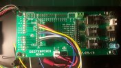
Sorry if this is all a bit dense, in both meanings but I do not have the confidence to install with the apparent conflicts and omissions I am presented with. Self inflicted in all probability. Max
Loco PCB without dummy DC PCB

Loco PCB with dummy in place

RCS full installation sheet, specific to installs using the Sierra card and SSI-9. I am using the supplied Cobra ESC

Bachmann PCB schematic

Just a little P.S.The component set supplied also includes one of their neat battery PnP's, to replace the dummy DC PCB's. It apparently allows the full functionality of the PCB to be employed. One problem RCS have not updated their Install instructions to demonstrate its incorporation in one involving a Sierra card and SSI-9. I do not intend to use it unless there is a very good reason to. Here is an image of how it would look if installed. I get the motor + & - inputs and I can understand the wires intended for connecting front and rear lights to marked outputs on the ESC for directional operation. It's the 2 middle ones, black and blue that go into the ground and decoder pins that have me mystified.

Sorry if this is all a bit dense, in both meanings but I do not have the confidence to install with the apparent conflicts and omissions I am presented with. Self inflicted in all probability. Max

