Converting an older U-class 2073D to digital

idlemarvel

Neither idle nor a marvel
13 Jul 2015
3,136
801
Ascot
Country
Mars
Best answers
0
Country flag
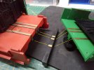
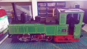
I've been looking for a green U-class for a while now. I bought this loco off eBay at a very reasonable price. Whether it is a bargain will have to wait until I try running it.
IMG_20210225_144854.jpg

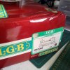
The 2073D is quite old, 40 years-ish, and is analog DC with no pretence at being DCC ready. This model has been well used and there a few things missing externally - doors most noticeably, and whistle - but otherwise in quite good nick. The (red) box is a bit crushed but not too bad.
IMG_20210225_144924.jpg

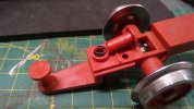
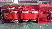
Looking underneath, these older U-class models have no skates, but some models like this one have metal pony wheels and pickups off those, so I'm hoping this will mean less trouble stalling on points. In general I prefer to remove skates where possible but I find my other U-class locos need them unless you fit a stay-alive. Traction tire looks okay but I have spares so I'll probably change it anyway.
IMG_20210225_144942.jpg

The previous or a previous owner has renumbered the loco from 298-14 to just 13, not sure why. This is what the prototype looks like or rather looked like in 1976:

als-oesterreichische-dampflok-29814-auf-565106.jpg


And in rather drab black on the Steyrtalbahn 5 years earlier:

29814-gruenburg-1-august-1968-69059.jpg


First job is to dismantle and clean the loco. More pictures of that process to follow.
 
Last edited:

rhaetianfan

RhB (obviously) but otherwise any 'modern' locos
24 Oct 2009
193
64
Hamble
Best answers
0
Country flag
I'll be interested to see how you get on, Dave. I have a Zillertal black version of the same vintage (1978) which I have never converted, bought it secondhand back in 1995 when I first started out. Despite its age and the fact that I now run on DCC, it has tended to be my loco of choice for testing. As you say, the lack of skates is compensated for by the pickups on the rear pony truck - as long as the wheels are clean it runs really well.

It will be the last of the collection to go, if ever I give up the hobby - it may not be RhB but I remember seeing the real loco in regular service in snowy Mayrhoffen in 1965!

M
 

idlemarvel

Neither idle nor a marvel
13 Jul 2015
3,136
801
Ascot
Country
Mars
Best answers
0
Country flag
Okay, warning this is a long posting, as I am going to post pictures of every stage of dismantling the loco, in case it may help others, but also to remind me when I try and put it back together!

Locos of this vintage use large stainless steel flat head screws, not smaller blackened cross head used more recently. You will need a hefty screwdriver.

First the coupling from the rear:

IMG_20210225_163733.jpg

Then remove the two screws from the back - they are amazingly long, 20mm, we'll see why later.

IMG_20210225_163628.jpg

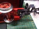
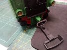
Then the pony truck. Watch out for the two brush contacts and springs!

IMG_20210225_164018.jpg

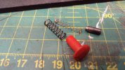
Note there will be three springs, two smaller ones for the brushes and one that applies downward pressure on the pony truck.

IMG_20210225_164559.jpg

The pony truck spring goes here:

IMG_20210225_164521.jpg

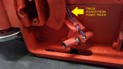
You can now see the two wires that collect the track power from the pony truck:

IMG_20210225_164724.jpg

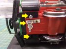
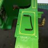
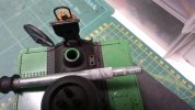
While we're underneath, at the front of the loco unscrew the smoke generator switch (metal strip) and the front snow-plough.

IMG_20210225_163830.jpg

More to follow...
 
Last edited:
  • Like
Reactions: 1 user

idlemarvel

Neither idle nor a marvel
13 Jul 2015
3,136
801
Ascot
Country
Mars
Best answers
0
Country flag
Part two...

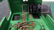
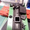
Now you can remove the cab. Pull it away at the bottom of the back and tilt it forwards until it comes away from the top of the boiler. The inside looks like this with some rather amusing cartoon like drawings of tools on the back wall, and brass strips everywhere.

IMG_20210225_164925.jpg

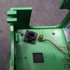
When you remove the cab you will see a large plastic block with brass strips around it. This is to provide electrical continuity between the chassis and the cab, quirky or ingenious according to your taste. This is why the long screws to attach the cab, mentioned earlier, as they have to pass through this block as well.

IMG_20210225_164829.jpg

To remove the cover over the wiring at the back of the cab you need to pull out the rear lamps to reveal two screws:

IMG_20210225_165045.jpg

You can also pull out the rear buffer:

IMG_20210225_165553.jpg

The inside of the cab with the inner cover removed looks like this:

IMG_20210225_165302.jpg

You can gently pull out the cab light from the roof mounting which lets you then prise out the ventilator hatch.

IMG_20210225_165651.jpg

The cab handles are plastic inserted through holes in the cab then sealed by melting the plastic on the end. (This may have been done by a previous owner or the factory I don't know which). Cut the melted ends off on the inside of the cab and remove the handles.

IMG_20210225_165812.jpg

You can remove the glazing by pushing gently and the glue should give way after 40 years of service!

IMG_20210225_170037.jpg

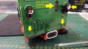
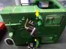
Now to remove the body from the chassis. There are two screws hidden behind the firebox front:

IMG_20210225_171107.jpg

Remove these, then unscrew the chimney. Look out for the nut falling off the bottom of the loco.

IMG_20210225_174153.jpg

You should now be able to slide out the front coupling loop.

IMG_20210225_174248.jpg

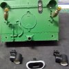
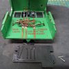
Now you can lift off the body. Inside the body are three weights which you can remove, two screws with washers each.
There are also some screw contacts which when the body is in place complete the circuit - again quirky or ingenious.

IMG_20210225_174516.jpg

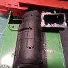
Under the weights tucked inside the steam dome is the sophisticated circuitry employed by this loco - two diodes to control the directional lights.

IMG_20210225_175117.jpg

Most of the details on the boiler can be removed, by pulling or prising, but some items like the generator and the boiler-top coal bunker are glued on (again I don't know if this was by a previous owner or at the factory).

IMG_20210225_175949.jpg

IMG_20210225_180254.jpg

Next, on to the motor. To be continued...
 
Last edited:
  • Like
Reactions: 1 user

AustrianNG

Director of my railway
16 Sep 2015
1,397
1,721
Wirral
Best answers
0
Country flag
Watching with interest Dave.

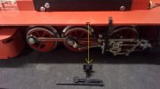
Please note - in the first picture of this thread, the motion behind the piston chest isn't sitting right - have a look at the photos of the real loco - you will see what I mean.
A little job to do on re-assembly.......;)
 

idlemarvel

Neither idle nor a marvel
13 Jul 2015
3,136
801
Ascot
Country
Mars
Best answers
0
Country flag
Watching with interest Dave.

Please note - in the first picture of this thread, the motion behind the piston chest isn't sitting right - have a look at the photos of the real loco - you will see what I mean.
A little job to do on re-assembly.......;)
Thanks Paul, I am going to remove the coupling and valve motion completely and reassemble. See next lot of pictures coming up.
 

idlemarvel

Neither idle nor a marvel
13 Jul 2015
3,136
801
Ascot
Country
Mars
Best answers
0
Country flag
Part three - motor

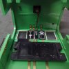
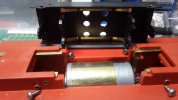
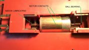
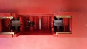
To open the motor lid there are six screws to undo - note that the lid is not the same inside at each end, one end has longer protrusions to hold the motor power contacts against the power supply brass strips.

IMG_20210225_181009.jpg

Inside you can just make out the ball bearings at the ends of the motor shaft:

IMG_20210225_181110.jpg

With some trepidation I lifted the motor out:

IMG_20210226_124134.jpg

The left hand gear looks a bit worn but it may just be excess dirt and oil. Note that the middle axle free-wheels.

Now for the motion / valve gear. Slide off this piece first:

IMG_20210225_174633.jpg

Then you need a nut driver / nut spinner to remove the motion / valve gear.

IMG_20210226_133811.jpg

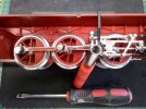
Now stripped down to the basics. If you wanted to open up the motor, the chassis / motor block is in two halves with six screws holding it together, two above and four below the "waterline".

IMG_20210226_135729.jpg

You can see the two above and one below to the left of the left wheel. The other three are behind the wheels so you would have to remove the wheels to get to the screws. This is a step too far for my purposes, but if you do be very careful with the brushes and springs behind each wheel rim, they can fly an exceedingly long way.

You can prise off the black brake block between the left and middle wheel. I had to trim some adhesive off to remove it, may not the be case with yours.

So that is the loco stripped down. You don't have to go as far as I have in dismantling it but you would certainly need to get to the motor if you want to rewire for DCC, which is my next job.
 
Last edited:
  • Like
Reactions: 1 user

idlemarvel

Neither idle nor a marvel
13 Jul 2015
3,136
801
Ascot
Country
Mars
Best answers
0
Country flag
Next, planning for DCC conversion.

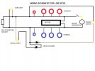
This is a schematic of the wiring in the DC analog loco:

circuitry.jpg
As it stands, the cab light and the multi-purpose socket are always on, the front or rear lights are on depending on current flow / direction, and the smoke generator is on or off depending on the position of the switch under the front of the loco. The motor goes faster or slower according to the voltage applied, and the lights brighter/dimmer. Such is life with DC analog. Most of this will have to go, but I may retain the "wiring" (brass strips) for the rear lights and cab light as it is quite a neat way to avoid trapped wires and plugging/unplugging wires should you want to remove the cab again.

The motor decoder will be connected to the track power so I can keep most of the power pickup "infrastructure" but the motor will have to be wired up separately and isolated from the track power brass strips. I think this can be done reasonably easily.

The smoke generator will need to be attached to the motor decoder so it can be controlled from there.

I haven't quite decided on the decoder yet. I have a spare LGB large motor decoder and a Massoth S for sound, so that is the likely route. I also have a firebox light which I think I will fit.

This thread may go quiet for a bit while I cogitate and find the time to progress this.
 
  • Like
Reactions: 1 user

idlemarvel

Neither idle nor a marvel
13 Jul 2015
3,136
801
Ascot
Country
Mars
Best answers
0
Country flag
I found an hour or two today and started the DCC conversion.

I first ran the loco on rolling road under DC "as is". Some squeaking and squealing initially but the poor thing hadn't had any lube for some time by the sound of it. Liberal dose of grease to the gears and oil to the joints and it was a lot better.
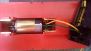
Then I took the motor out and soldered green and yellow wires to the tabs, covering up the tabs and any exposed solder with some earthing sleeve. This is to stop it coming into contact with the track power directly. I drilled a few holes in the motor cover directly above where the wires were attached and fed them through, see below:

IMG_20210228_163308.jpg

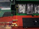
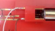
At the rear end I cut the brass strips to remove the direct track power feed to the rear and cab lights, and soldered brown and white wires to the exposed tabs. This is the track power "bus" from all the wheels.

IMG_20210228_163318.jpg

When you replace the motor you will notice a small lug on one end that fits in a slot in the bottom of the motor cradle. I replaced the motor cover, taking care not to get the wires tangled inside the motor block or touching the gears, and making sure the outer wheels were aligned with each other. Press well down on the cover while screwing it one to make sure the motor worm drive is firmly meshing with the gears.

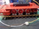
To test it again on DC, just connect the white and yellow, and green and brown wires, and apply some juice.

IMG_20210228_163941.jpg

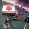
I kept my simple PIKO analog controller and transformer from the first starter set I bought, it's ideal for this kind of work. The motor runs quite well, starting on about 2.5 volts, but it is probably past it's best, Luckily the demands of my layout are very simple, no grades or long trains to pull. While the coupling rods were removed I took the opportunity to clean the wheels and replace the traction tire.

IMG_20210228_165241.jpg

In the foreground you can see the LGB two motor decoder that I plan to install as the next step.
 

idlemarvel

Neither idle nor a marvel
13 Jul 2015
3,136
801
Ascot
Country
Mars
Best answers
0
Country flag
I was hoping not to have to open the motor, but the rear left pickup wasn't working, and it wasn't the brush or spring, and the loco still made too much noise when running, even though the motor on its own was almost silent. So something amiss inside. With courage in one hand and large screwdriver in the other, I took off all the wheels and opened up the case.

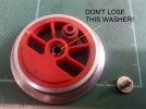
When you take off the wheels be careful not to lose the power pickup brushes and springs. Also note that behind the wheel screw there is a very small washer:

IMG_20210302_105421.jpg

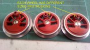
The wheels all have different length protrusions, longest goes in the centre wheel, shortest at the back, medium at the front.

IMG_20210302_105504.jpg

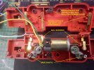
This is what the inside looks like when the two halves are opened. Don't lose those ball bearings!

IMG_20210302_105255.jpg

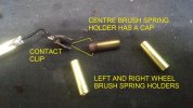
The problem with the pickup was that the brass strap was not pushing against the brass cylinder that holds the power pickup brush and spring. FYI the brass cylinders for the centre wheel power pickups and brushes have a cap on the end, and power is transmitted via a spring clip (needs a good clean) rather than a brass strip:

IMG_20210302_111350.jpg

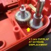
I'm not 100% sure where the noise is coming from, as all the drive shafts move freely and all the gears looks in good shape. I think it may be because the overlap between the intermediate cog wheel between the worm gear and the drive shaft gear is very small, less than 1 mm maybe even 0.5 mm. I can imagine at speed that might cause some noise and at load might even slip a notch. Bit hard to see in the picture:

IMG_20210302_105349.jpg

So I plan to move the drive shaft gear along a mm or two to make the overlap bigger, to see if that solves the problem. You can't move it too far otherwise it will rub against the larger cog wheel at extreme displacement the other way.

I have now taken the loco apart to the last nut and bolt - well not quite, I haven't dismantled the valve gear - so I thought it would be a good time to give it all a damn good clean in the dishwasher while no-one's looking.

IMG_20210302_115724.jpg
 

phils2um

Phil S
11 Sep 2015
1,522
423
Ann Arbor, Michigan
Country
United-States
Best answers
0
Country flag
HI Dave,

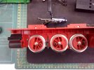
Just wanted to show how I used the existing bus bars when I chipped my 2070D. It is the same vintage as the U-lok you are working on. It may be useful to you. The ESU LokPilot V4.0 XL decoder is quite a bit smaller than the LGB decoder you're planning to use and fits nicely in the U43's body.

U43 decoder - 1.jpeg U43 decoder - 1 (1).jpegU43 decoder - 1 (2).jpeg U43 decoder - 1 (3).jpeg

I didn't include a pic of the cab. I don't remember if I made any changes there. If I did, it was to rearrange the rear light and cab light wires to make sure they contact with the correct re-wired bus bars.
 
Last edited:
idlemarvel

Neither idle nor a marvel
13 Jul 2015
3,136
801
Ascot
Country
Mars
Best answers
0
Country flag
Thanks Phil that's useful info.
 

idlemarvel

Neither idle nor a marvel
13 Jul 2015
3,136
801
Ascot
Country
Mars
Best answers
0
Country flag
No pictures today, but some progress.

I tried to move the cog wheel on the drive axles along a millimetre but it would not budge, and I didn't want to use more force for fear of damage. In the end I fitted a small washer between the cog and the body wall, which had the same effect. Reassembled the loco and ran it on the rolling road, and she ran as sweet as a nut and with a lower starting voltage and better low speed performance, so well worth the time spent. Now to reattach the coupling bars / valve gear. They need a touch of paint first though.

Ref P phils2um comments above, I have decided to use an XL decoder on it's side alongside the motor block, as there is no room for the bulky LGB decoder unless you remove a weight. There is barely space for a wire between the top of the motor housing and the bottom of the weights. I may have to leave one weight out anyway to make space for a speaker, but I have a thin speaker that may fit in the cab roof as an alternative.
 

idlemarvel

Neither idle nor a marvel
13 Jul 2015
3,136
801
Ascot
Country
Mars
Best answers
0
Country flag
I re-attached the coupling rods and valve gear for a test run on the rolling road today.

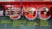
It was easier than I thought it would be to put this all back. There are 3 screws each side and 3 washers, 2 with small apertures and 1 with larger aperture.

First reattach the coupling rods without the driver and valve gear. This lets you test to make sure the wheels are aligned correctly, and it is almost impossible to fit the screw to the front wheel once the valve gear is in place. Test run video:


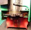
Now attach the valve gear. Insert the pistons into the cylinders, clip the frames on the side, and make sure the valve gear is lined up correctly, see picture below.

IMG_20210304_104904.jpg

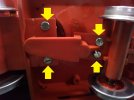
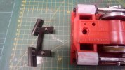
Once you are happy all is in place properly on both sides, you can fit the front snowplough, the screws of which also hold the cylinder covers in place.

IMG_20210304_104711.jpg

The cylinders have been painted with primer sprayed into a lid. As supplied to me the cylinders were unpainted but wrapped in black insulating tape. I decided black paint would look better. Also on cosmetics, the front snow plough will be modified as it is not like the prototype which has a fixed bar across the front, see pictures in post #1.

Now to test the valve gear on the rolling road.


Looks good to me, now some painting while I wait for the XL decoder to arrive.
 

idlemarvel

Neither idle nor a marvel
13 Jul 2015
3,136
801
Ascot
Country
Mars
Best answers
0
Country flag
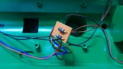
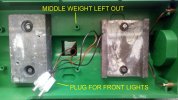
Massoth XL decoder arrived so now to find somewhere convenient to put it. Not enough room down the side of the motor block (a Massoth L would probably have fitted) so no real alternative than to lose one of the weights and fit it on top of the motor block. Before that, though, some preparation soldering. The front lights will be attached via a plug to make removing the body shell easier.

IMG_20210307_131040.jpg

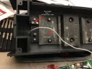
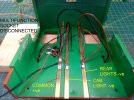
The rear and cab lights re-soldered to the "bus bars" in the cab:

IMG_20210307_124829.jpg

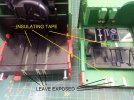
The offending bus-bars covered with insulating tape. The green is quite a good colour match.

IMG_20210308_113605.jpg

Now the decoder can be wired up. I prefer the Massoth XL to the L as it has screw connectors and for some reason it is marginally cheaper.

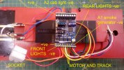
IMG_20210307_140947.jpg

I attached the cab light to A2 rather than LI-C so that I could control it separate from the directional lights. The socket for the front lights will be attached to the motor block in the space to the right of the decoder. I will secure the various wires before putting the body shell back on. If I do get around to adding sound I will use the SUSI connector on the XL and put the speaker in the cab roof, or there's room for a small speaker behind the firebox frontage.

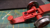
I did some testing to make sure all the lights and smoke generator worked. I found that even with all the weights in, the spring in the rear pony truck is so strong it still lifts the rear driver wheel off the track slightly, which causes problems reversing over R1 curves and points. I understand that it needs to be forceful to maintain rail contact for the pony truck pickups to work, but a bit too much I feel. I took the spring out - it is 17mm long unstressed, and cut off 3mm from one end. That seems to do the trick.

Now to do some decoder tuning and finish the cosmetic work. I made some doors out of plasticard but I just could not get colour to match the green. I have the entire Humbrol range of greens - the closest is No 2 gloss green - which is okay for touch-ups but not for a whole panel. I tried mixing something but never got close. As a last resort I looked at modell-land,de to see if they had any green doors for a 207x and by some miracle they have one of each left and right. I just hope it is the same green. Bit pricey with €28 P&P to UK but I had some other bits I wanted so not too bad.

To be continued.
 
  • Like
Reactions: 1 users

Software Tools

Registered
18 Jan 2013
304
53
Sydney, Australia
Best answers
0
Country flag
You might want to check that all the driving wheels are actually making good contact with the track. The trailing truck spring in the early 2073x locos was a bit strong and tended to lift the rear drivers just clear of the rails.

Sniping a coil or two of the spring reduces the rear truck springing pressure and allows all the driving wheels to have good contact with the rails., which in turn improves both tractive effort and electrical pickup.

1615282053107.png
 
Last edited:
  • Like
Reactions: 1 user
idlemarvel

Neither idle nor a marvel
13 Jul 2015
3,136
801
Ascot
Country
Mars
Best answers
0
Country flag
You might want to check that all the driving wheels are actually making good contact with the track. The trailing truck spring in the early 2073x locos was a bit strong and tended to lift the rear drivers just clear of the rails.

Sniping a coil or two of the spring reduces the rear truck springing pressure and allows all the driving wheels to have good contact with the rails., which in turn improves both tractive effort and electrical pickup.

View attachment 282052
Thanks for the tip. It helps a lot.
 

curtis

Registered
27 Nov 2018
438
115
34
Jersey
Country
Jersey
hsbagardenrailway.com
Best answers
0
Country flag
Thanks for the tip. It helps a lot.
Did Spreewalds also have a challenge with their spring - I note they have a similar arrangement of wheels (but inverses)? I have a Spreewald where the pilot wheels won't turn when on the rails (free wheels fine when done by hand). I replaced the spring but had the same effect
 

PhilP

G Scale, 7/8th's, Electronics
5 Jun 2013
33,546
3,520
Nottingham
Best answers
0
Country flag
Check the back to back on the pony truck..

I found it was way too wide.