Ricky no worries, I know this is a labour of spare time so as and when. Many thanks for the update and your work thus far.Just wanted to say this hasn't been forgotten about, I had a really busy week last week so hadn't made much progress but I have had the chance to put in a few of hours in the last couple of days
You are using an out of date browser. It may not display this or other websites correctly.
You should upgrade or use an alternative browser.
You should upgrade or use an alternative browser.
Combino Duo Tram
- Thread starter dunnyrail
- Start date
musket the dog
Registered
Hi again,
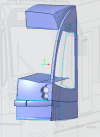
A quick update on where the tram currently stands. It doesn't look like a lot of progress again, but there probably 3-4 more hours. It took a lot of back and forth to get the bumper and coupling cover to look 'right'. Still not sure I'm there so please let me know if you can spot a panel that is well out of place. The drawings don't quite have the level of detail so I've been trying my best to interpret the photos.
I think it's starting to look like half a cab. Of course it's still just the outer skin at the moment. I'll try and complete a step by step for the latest too, I went back over what had been done and tweaked so many parts that the order of my screenshots is a little bit confused. Still enjoying the project though, I really do enjoy CAD design when I get back into the swing of it, it's much nicer without the looming production deadlines too

I think if you are getting a bit off track it may be to do with the depth of the bumper to my eye, I flopped back n fro from the two and that was what hit my eye. So little though I would think. But so many thanks for whet you are taking your time in.Hi again,
A quick update on where the tram currently stands. It doesn't look like a lot of progress again, but there probably 3-4 more hours. It took a lot of back and forth to get the bumper and coupling cover to look 'right'. Still not sure I'm there so please let me know if you can spot a panel that is well out of place. The drawings don't quite have the level of detail so I've been trying my best to interpret the photos.
I think it's starting to look like half a cab. Of course it's still just the outer skin at the moment. I'll try and complete a step by step for the latest too, I went back over what had been done and tweaked so many parts that the order of my screenshots is a little bit confused. Still enjoying the project though, I really do enjoy CAD design when I get back into the swing of it, it's much nicer without the looming production deadlines too
View attachment 273326
casey jones snr
Registered
Jon and Ricky, how is this project progressing? It’s been very interesting so far.
I am not pushing Ricky as he is doing things as and when he can.Jon and Ricky, how is this project progressing? It’s been very interesting so far.
musket the dog
Registered
I have been doing little half hours here and there in the background just nothing big enough to warrant and update yet I thought  My attention span for sitting down and doing CAD work at home is quite dependant on how much of it I've had to do at work. However I've been on the tools for the last couple of weeks so I've been looking forward to finding some time in the evenings to come home and do some design. Update soon
musket the dog
Registered
Evening all,
I would think it's about time for a long overdue update on this project. I have been working away in the background but the trouble is when all the big pieces are fleshed out in their basic form you then have to start sinking a lot of time into tweaking. Tonight for example I have done about another hour of modelling, I would say a third of that was actually building new surfaces. The rest is spent reordering and reassessing what I had already done to make the (CAD) model more stable and better prepare it for its transition from 2D to 3D.
I won't bore everyone with the blow-by-blow but I'll try and give a flavour of what goes on.
The first thing I completed was the sides of the front section. This is a simple extrude of the outline of the rear most edge of the cab section.
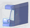
At the moment I am leaning towards making the windows and doors as separate components. To prepare for this I needed holes in the surface to accept them. As with the previous steps, the outlines were sketched onto the drawing and projected onto the surface. I could then trim the side panel to remove the unwanted surface.
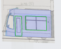
At the same time I used the same method to add the panel lines onto the surface. I will leave these for now and come back to them at a later point.
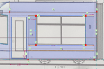
I would think it's about time for a long overdue update on this project. I have been working away in the background but the trouble is when all the big pieces are fleshed out in their basic form you then have to start sinking a lot of time into tweaking. Tonight for example I have done about another hour of modelling, I would say a third of that was actually building new surfaces. The rest is spent reordering and reassessing what I had already done to make the (CAD) model more stable and better prepare it for its transition from 2D to 3D.
I won't bore everyone with the blow-by-blow but I'll try and give a flavour of what goes on.
The first thing I completed was the sides of the front section. This is a simple extrude of the outline of the rear most edge of the cab section.

At the moment I am leaning towards making the windows and doors as separate components. To prepare for this I needed holes in the surface to accept them. As with the previous steps, the outlines were sketched onto the drawing and projected onto the surface. I could then trim the side panel to remove the unwanted surface.

At the same time I used the same method to add the panel lines onto the surface. I will leave these for now and come back to them at a later point.

musket the dog
Registered
I then knocked the model back a few steps to hide off the sides while I returned to working on the front end.
I had tweaked the front bumper to make it sit a bit prouder from the front panel. My thinking is that the bumper will be a seperate piece to be fixed into the front end. This meant I needed to create a pocket for it to sit in on the front panel.
Working with the front bumper, which exists as its own surfaces unattached to the rest of the cab, I select the 3 edges that will sit through the panel. I can the create an small offset of these 3 surfaces to create the beginnings of the pocket.
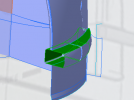
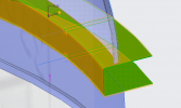
As the cab existed at this point as one lump, with all of its surfaces merged together I could simply merge the offset of the bumper and the cab to trim all of the panels back to create the pocket.
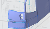
However, this left a problem; because all the cab was one piece when I did the merge I now have a big U-section cutting through the whole thing. I don't want the pocket to cut through the side as it's quite clear looking at the pictures of the prototype the bumper overlaps the side panels.
I would need to go back and reorder a few things so that I cut the front panel but not the sides with the merge. However, if I leave the panel intact but still as a 2D surface I'll cause myself issues later. When I add thickness to everything I will offset the whole cab as one piece to create the 3D model. All these new surfaces will go behind what currently exists. If I were to fill in the missing square on the side panel, I would be trying to add material in a different direction, which would cause the offset to fail...
I had tweaked the front bumper to make it sit a bit prouder from the front panel. My thinking is that the bumper will be a seperate piece to be fixed into the front end. This meant I needed to create a pocket for it to sit in on the front panel.
Working with the front bumper, which exists as its own surfaces unattached to the rest of the cab, I select the 3 edges that will sit through the panel. I can the create an small offset of these 3 surfaces to create the beginnings of the pocket.


As the cab existed at this point as one lump, with all of its surfaces merged together I could simply merge the offset of the bumper and the cab to trim all of the panels back to create the pocket.

However, this left a problem; because all the cab was one piece when I did the merge I now have a big U-section cutting through the whole thing. I don't want the pocket to cut through the side as it's quite clear looking at the pictures of the prototype the bumper overlaps the side panels.
I would need to go back and reorder a few things so that I cut the front panel but not the sides with the merge. However, if I leave the panel intact but still as a 2D surface I'll cause myself issues later. When I add thickness to everything I will offset the whole cab as one piece to create the 3D model. All these new surfaces will go behind what currently exists. If I were to fill in the missing square on the side panel, I would be trying to add material in a different direction, which would cause the offset to fail...
musket the dog
Registered
So to fix it...
In my previous role at work when designing complex shapes like body panels made from scanned data we could easily spend a week or more going back over a near complete part, tweaking and tuning, trying to make everything stable and free of build errors.
In a parametric CAD program, like CREO (used here), Autodesk or Solidworks you build the finished product up, bit by bit, through various features. These exist as timeline in the file. I can roll back the model to any point and start work again and insert new features. I can edit any no matter how many exist after it. Importantly for fixing the issue above, I can move the individual features around in this timeline. The Combino currently exists as 240 features.
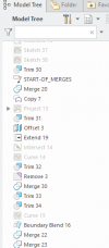
As identified above I would need to move the merge for the bumper pocket to be before the merges for the cab. Before I had created one merge that joined all 8 panels for the cab at once. I now needed to consider the order I did this a little more carefully.
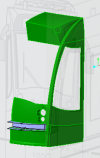
The new first merge was to create the full side panel from its components. I could then make a copy of this and trim the copy back to the area I was interested in. To begin to make the wall I needed on the inside of the panel I offset the remainder of the copy by 2mm.
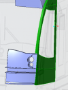
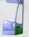
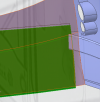
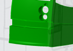
I can then create the curve from the intersection of the offset panel and the bumper. I need to fill in the curve the arrow points to in order to create a loop. I can then trim the whole offset panel back to the section scribbled over in blue. The then becomes the new side wall of the pocket and I can merge to two parts together.
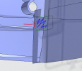
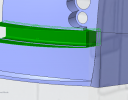
I then need to fill in the gap left in the front panel.
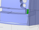
I can then go about remerging the front end back together.This time I have left it as a series of separate features in order.
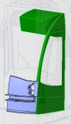
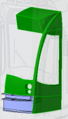
In my previous role at work when designing complex shapes like body panels made from scanned data we could easily spend a week or more going back over a near complete part, tweaking and tuning, trying to make everything stable and free of build errors.
In a parametric CAD program, like CREO (used here), Autodesk or Solidworks you build the finished product up, bit by bit, through various features. These exist as timeline in the file. I can roll back the model to any point and start work again and insert new features. I can edit any no matter how many exist after it. Importantly for fixing the issue above, I can move the individual features around in this timeline. The Combino currently exists as 240 features.

As identified above I would need to move the merge for the bumper pocket to be before the merges for the cab. Before I had created one merge that joined all 8 panels for the cab at once. I now needed to consider the order I did this a little more carefully.
The new first merge was to create the full side panel from its components. I could then make a copy of this and trim the copy back to the area I was interested in. To begin to make the wall I needed on the inside of the panel I offset the remainder of the copy by 2mm.


I can then create the curve from the intersection of the offset panel and the bumper. I need to fill in the curve the arrow points to in order to create a loop. I can then trim the whole offset panel back to the section scribbled over in blue. The then becomes the new side wall of the pocket and I can merge to two parts together.


I then need to fill in the gap left in the front panel.

I can then go about remerging the front end back together.This time I have left it as a series of separate features in order.


musket the dog
Registered
Well done if you have made it this far, I promise that's the last of the dull stuff for tonight. To round off this is where the front section currently stands; minus the bumper, which I have hidden off.
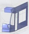
The next step will be to add the roof and then start offsetting the surfaces to build a 3D model. I expect this will need a lot of coaxing to make a success. I will then look at how to split ap all the body panels in a way that would be suitable for printing.

The next step will be to add the roof and then start offsetting the surfaces to build a 3D model. I expect this will need a lot of coaxing to make a success. I will then look at how to split ap all the body panels in a way that would be suitable for printing.
As ever Ricky wow. I get lost for superlatives to describe the hard work and complexity of the challenge. But looking at post #27 I can see a small glimmer of light at the end of a very very long tunnel. I am begining to see that one day there will be a battery powered version trundling around my Harz line. That is indeed a mouth watering prospect, as ever I will then need some help as to who or how I get one printed.
casey jones snr
Registered
Brilliant stuff Ricky.
musket the dog
Registered
I had hoped to have really cracked on with this but all the free time I thought I would have over the Christmas break never really materialised . I have managed to put a few more hours in and think I'm starting to get near to the end of the basic body shell.
Update this weekend
Update this weekend
musket the dog
Registered
Evening everyone,
Another update from the everlasting project to recreate a Combino tram in the digital world. The hours I have been putting in here and there of late have been aimed at turning the surfaces built above into a solid 3D mass. The CAD program does allow to offset a surface and fill in the sides but it gets harder as there are more surfaces, corners, edges and eventually it can't generate the offset surface. The only way I know so far to get around this is to try and offset the whole surface and then go through suspect areas telling the program to ignore them, one by one, until it works.
For something simple like the side this works fine. The whole piece can be done in one go and I know that all the edges of the new piece are going to be exactly lined up with the existing outer surface. I've gone with 2mm for the wall thickness.
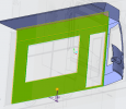
As a general rule of thumb, if it is difficult to create in the first place it will cause trouble when you try to offset it. In total I had to exclude 23 individual pieces to get the front end to offset.
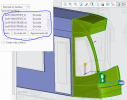
I will use a number of methods to fill in the gaps. Some larger pieces like the headlight cowl can be offset on their own in a separate feature and then merged back to the main part. Smaller holes will be filled in using blends later on.
Some need to be completely reconstructed, as I had to do with the front bumper pocket.
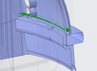
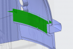
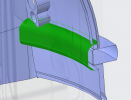
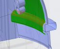
Another update from the everlasting project to recreate a Combino tram in the digital world. The hours I have been putting in here and there of late have been aimed at turning the surfaces built above into a solid 3D mass. The CAD program does allow to offset a surface and fill in the sides but it gets harder as there are more surfaces, corners, edges and eventually it can't generate the offset surface. The only way I know so far to get around this is to try and offset the whole surface and then go through suspect areas telling the program to ignore them, one by one, until it works.
For something simple like the side this works fine. The whole piece can be done in one go and I know that all the edges of the new piece are going to be exactly lined up with the existing outer surface. I've gone with 2mm for the wall thickness.

As a general rule of thumb, if it is difficult to create in the first place it will cause trouble when you try to offset it. In total I had to exclude 23 individual pieces to get the front end to offset.

I will use a number of methods to fill in the gaps. Some larger pieces like the headlight cowl can be offset on their own in a separate feature and then merged back to the main part. Smaller holes will be filled in using blends later on.
Some need to be completely reconstructed, as I had to do with the front bumper pocket.


musket the dog
Registered
Being perfectly honest, this is the part of the 3D modelling I enjoy the least and I've procrastinated at home exactly as I would do at work  I won't go through every little detail of what had to be done but I'll run through a couple more examples below.
Some surfaces don't quite come together as they should, or because of what has been excluded the edges of some offsets are not always square. The latter has caused me to be left with this triangular hole in the headlight cowl. The program can create triangular surfaces between the edges but they are not very stable. When it's computing the digital mesh from the surface everything is done in squares (more specifically quadrilaterals) running across the surface. If the surface only has three edges all these squares have to bunch up in one of the corners which makes the part less reliable and the feature more likely to fail. The robust way to solve this is to cut a rectangle out of your triangular hole and fill it in.
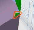
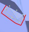
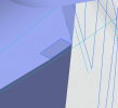
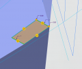
The little orange symbols with a circle tangent to a line are showing where I have constrained the new surface to be tangent to the existing one.
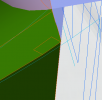
Some surfaces don't quite come together as they should, or because of what has been excluded the edges of some offsets are not always square. The latter has caused me to be left with this triangular hole in the headlight cowl. The program can create triangular surfaces between the edges but they are not very stable. When it's computing the digital mesh from the surface everything is done in squares (more specifically quadrilaterals) running across the surface. If the surface only has three edges all these squares have to bunch up in one of the corners which makes the part less reliable and the feature more likely to fail. The robust way to solve this is to cut a rectangle out of your triangular hole and fill it in.


The little orange symbols with a circle tangent to a line are showing where I have constrained the new surface to be tangent to the existing one.

Last edited:
musket the dog
Registered
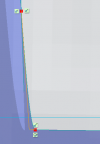
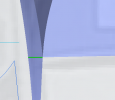
Sometimes, for no particular reason, the offset surface freaks out completely and inverts itself. This happened to the inside wall of the windscreen frame. The long 'V' shape in the picture below is where the 2D surface has completely flipped around, gone back to front and rolled back again. Sometimes this can't been seen and will happily exist in the model until you try to convert everything to 3D. At which point the geometry becomes impossible. I believe this is why some programs that work almost completely in surfaces, such as SketchUp can come to have meshing issues when people try to 3D print with them.
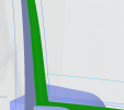
The easiest way to fix this is to cut it out and rebuild it. I've got one good edge in the corner of the panel so I copy and paste that so I can work from it once I have cut away the bad.
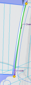
Next I cut away the curve at the bottom to leave a nice square corner I can pick up on later. And then add a line to cut across at the top.
Using the same methods I used to create the original wire frame of the body, I intersect two curves to build the new inner windscreen edge. Finally I can blend a surface between the 4 edges.
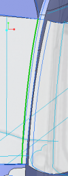
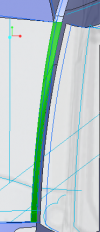

The easiest way to fix this is to cut it out and rebuild it. I've got one good edge in the corner of the panel so I copy and paste that so I can work from it once I have cut away the bad.

Next I cut away the curve at the bottom to leave a nice square corner I can pick up on later. And then add a line to cut across at the top.


Using the same methods I used to create the original wire frame of the body, I intersect two curves to build the new inner windscreen edge. Finally I can blend a surface between the 4 edges.


musket the dog
Registered
So where are we now?
Admittedly it doesn't look that different to how it ended up in the previous round up but I would now consider that the hardest part is done. I've got a full 3D model with all the sides of the body of the Combino that I could solidify and print if I wanted to. I've still got a little tidying up to do around the headlight before I will be completely satisfied with it.
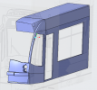
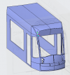
Next up I will make the doors and the large passenger window, then move on to figuring out how to retain the driver's glass. The floor can go in after that and then I'll move onto a representation of the roof furniture and things like body panel split lines.
I think for the best chance of a good print it will need to be split up into sections. The sides being nice and flat can be isolated. The roof if cut behind the headboard might print quite well stood up vertically. The front will be the trickiest but I'm thinking about how I can add supports that can be cut away after the print.
Again any feedback welcome including if there were any good ideas form suitable motor blocks.
Admittedly it doesn't look that different to how it ended up in the previous round up but I would now consider that the hardest part is done. I've got a full 3D model with all the sides of the body of the Combino that I could solidify and print if I wanted to. I've still got a little tidying up to do around the headlight before I will be completely satisfied with it.


Next up I will make the doors and the large passenger window, then move on to figuring out how to retain the driver's glass. The floor can go in after that and then I'll move onto a representation of the roof furniture and things like body panel split lines.
I think for the best chance of a good print it will need to be split up into sections. The sides being nice and flat can be isolated. The roof if cut behind the headboard might print quite well stood up vertically. The front will be the trickiest but I'm thinking about how I can add supports that can be cut away after the print.
Again any feedback welcome
Hi Monty, as ever a great job. Hope you do not invoice me by the hour! Joking aside a possibility for the chassis would be the IP Engineering chassis (£30) as below:-So where are we now?
Admittedly it doesn't look that different to how it ended up in the previous round up but I would now consider that the hardest part is done. I've got a full 3D model with all the sides of the body of the Combino that I could solidify and print if I wanted to. I've still got a little tidying up to do around the headlight before I will be completely satisfied with it.
View attachment 278858
View attachment 278859
Next up I will make the doors and the large passenger window, then move on to figuring out how to retain the driver's glass. The floor can go in after that and then I'll move onto a representation of the roof furniture and things like body panel split lines.
I think for the best chance of a good print it will need to be split up into sections. The sides being nice and flat can be isolated. The roof if cut behind the headboard might print quite well stood up vertically. The front will be the trickiest but I'm thinking about how I can add supports that can be cut away after the print.
Again any feedback welcomeincluding if there were any good ideas form suitable motor blocks.

6 to 12 volt 4wd Electric chassis Kit | IP Engineering
Budget 4WD Electric Chassis KitThis chassis provides a sound basis for scratch building your own locomotives. The main chassis is formed from ABS moulding wheels and axles are steel with brass wheel bearings and there is a worm drive to both axles. The tough electric motor will operate with 6...
There is also the Fosworks Motor and Wheelset essentially a single wheeled motor unit (£34 each). Inreckon at least a couple of would be required. You need to scroll a good way down to find them, he will also fit your wheels so smaller ones could be done.

Fosworks
Garden Railway Radio Control and Sound Radio DCC for Gauge 0 to Gauge 3 Analogue DC and live steam systems too
musket the dog
Registered
Hi Monty, as ever a great job. Hope you do not invoice me by the hour! Joking aside a possibility for the chassis would be the IP Engineering chassis (£30) as below:-

6 to 12 volt 4wd Electric chassis Kit | IP Engineering
Budget 4WD Electric Chassis KitThis chassis provides a sound basis for scratch building your own locomotives. The main chassis is formed from ABS moulding wheels and axles are steel with brass wheel bearings and there is a worm drive to both axles. The tough electric motor will operate with 6...www.ipenginnering.com
Don't worry, I'm still enjoying it at the moment and it's helping to sharpen some skills that have started to dull since I changed jobs. I'll only start to charge when I start to loose patience with it
I'd thought the IP gearbox might be a good choice too. I had worried that maybe it wouldn't be butch enough but in reality it shouldn't have too much work to do. I think I can make a pretty good representation of it from the measurements on the website. Once the floor is in I'll have a go at trying to get it in there.
Rhinochugger
Retired Oik
The depth of knowledge and level of skill here is frightening 

I'll stick to being a Luddite

Another alternative is the Swift Sixteen motor bogie that is adjustable in length

Builders Parts | Mysite a bit dearer
 but probably more robust
I'll stick to being a Luddite
Another alternative is the Swift Sixteen motor bogie that is adjustable in length
Builders Parts | Mysite a bit dearer
