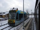
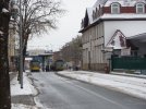
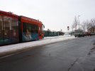
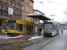
Combino Duo Tram

dunnyrail

DOGS, Garden Railways, Steam Trains, Jive Dancing,
Staff member
GSC Moderator
25 Oct 2009
26,171
4,993
75
St.Neots Cambridgeshire UK
Best answers
0
Country flag
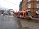
Hi stars if the 3D world, I have been for some time thinking that I would very much like a Harz Nordhausen Combino Duo Tram for my line in G scale. There is the North Pilton Flexicity that oerhaps could be modified but I fele that there would be an awful lot of filling and hacking to get this to look like a Harz Combino.


Then there is the 3D one that was found after a listing in one if the 3D links in the Forum. Again this is not quite right but a possibility as a couple of front sections and one of the centre sections could possibly work.


However more searching found the right thing available up to HO as a body only 3D via Shapways. Perfect if the scale could be sorted to 1:22.

EDIT FORGOT THE SHAPWAYS LINK:-


But here I fell over as I think that there must somewhere be a file that someone within the forum could get at and up to our scale, I am sure that there would be a need within the many Harz guys amongst us. If I could get Drawings to the right scale and an idea of a printer coy that would make a good job I would be happy to liaise and get some sorted at cost plus whatever it costs to post out.

Any helpers for the design and printing Co. please?
 
Last edited:

Gtarling

Registered
26 Aug 2019
76
8
74
Grantham
Best answers
0
Country flag
The 'slicer' programs used to generate the Gcode which the 3D printers use generally have a scaling function and this is probably the place to start - find the design you want in whatever scale is available and then see if a slicer like 'Cura' is able to scale it to the size you want - the rest is taken care of by the slicer and the 3D printer. My printer hasn't arrived yet, so perhaps someone else here could give it a try for you.
 

musket the dog

Registered
31 Oct 2009
787
143
Leicester
nlrr.webs.com
Best answers
0
Hi Jon,

I don't think that it would be likely to get the file out of Shapeways, as the vast majority of products on there are hosted to try and make a little bit (sometimes a lot) of money for the designer.

If you can get ahold of some decent drawings I would be happy to try and have a go at doing some design work on it. The majority looks simple enough but the front end might take a little time and surfacing work to get 'right'.

On my Shapeway store I have an option for people to contact me to request different sizes/scales of parts. It might be that the designer of the exisiting Duo tram has the same and might be willing to scale it up?

Many thanks,
Ricky
 

dunnyrail

DOGS, Garden Railways, Steam Trains, Jive Dancing,
Staff member
GSC Moderator
25 Oct 2009
26,171
4,993
75
St.Neots Cambridgeshire UK
Best answers
0
Country flag
Hi Jon,

I don't think that it would be likely to get the file out of Shapeways, as the vast majority of products on there are hosted to try and make a little bit (sometimes a lot) of money for the designer.

If you can get ahold of some decent drawings I would be happy to try and have a go at doing some design work on it. The majority looks simple enough but the front end might take a little time and surfacing work to get 'right'.

On my Shapeway store I have an option for people to contact me to request different sizes/scales of parts. It might be that the designer of the exisiting Duo tram has the same and might be willing to scale it up?

Many thanks,
Ricky
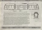
Thanks Ricky sound like a great offer, I have edited my original post as I forgot to include the Shapways link. Here is the only drawing that I have which I have tried to put G sizes on not too well scaled I fear. My thoughts have always gone along the lines of adapting the Cammon Drawings which are available as a download, the Flexicity Shapes appear very similar to the Combino just the location of windows that differ. Also the Flexicity is using a centre section for the power unit, I have in my mind trying to get hold of a North Pilton Flexicity mechanism for just one end which I think should be enough power. My own if this ever gets off the ground will be a Battery Powered jobby, I think that the roof profile ought to be a le to hide a multitude of stuff.

B4796E55-7E33-4497-805D-85098D424697.jpeg
 

musket the dog

Registered
31 Oct 2009
787
143
Leicester
nlrr.webs.com
Best answers
0
I spent a hour yesterday roughing up a quick copy of the front end. I've got try and mess around with some software at home but ultimately I think it looks possible, I think I've had some clever ideas with the glazing too. I'l try and share some screen shots soon :)
 

dunnyrail

DOGS, Garden Railways, Steam Trains, Jive Dancing,
Staff member
GSC Moderator
25 Oct 2009
26,171
4,993
75
St.Neots Cambridgeshire UK
Best answers
0
Country flag
I spent a hour yesterday roughing up a quick copy of the front end. I've got try and mess around with some software at home but ultimately I think it looks possible, I think I've had some clever ideas with the glazing too. I'l try and share some screen shots soon :)
Great Ricky so many thanks, looks like we may be onto something.
 

musket the dog

Registered
31 Oct 2009
787
143
Leicester
nlrr.webs.com
Best answers
0
I thought I would try and give a little update as to what I have been up to tonight. It doesn't look like a lot so far, but it's a couple hours of work of studying the drawings and searching for useful pictures. I thought I might try to give a little bit of a step-by-step to how someone might go about designing something like this :)

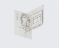
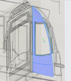
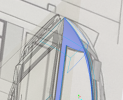
The first step is to get your references into the program. In my day job we still use full size clay models as the prototype surfaces for the vehicles. We would scan these in, and I would use the rough 3D data to build my surfaces. In this case, I took the drawing above, cut out and straightened the views and aligned and scaled them in the program.

1.PNG

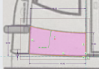
I am working from the large, straight and vertical line behind the driver's compartment. Using the drawing as a guide I can then sketch the outline of the first body panel, in the first direction.

2.PNG

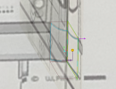
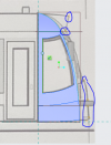
I then repeat this in the other direction, using the lines I made previously as references to make sure all the corners of the boxes have the same height from the ground plane.

3.PNG

Once I have the body panel drawn looking in 2 directions I can merge then to create the final outline of the panel, roughly where it should exist in 3D space.

4.PNG

I then repeat this basic process to create the outlines of all the body panels on one side of the driver's compartment.

5.PNG
 
  • Like
Reactions: 1 user

musket the dog

Registered
31 Oct 2009
787
143
Leicester
nlrr.webs.com
Best answers
0
It's worth noting at this point that when working on complex shapes like this I will work in what is referred to as 'surfaces'. Although the shapes exist in 3 dimensions, and can take on all the geometry of the outer skin of the final product, they have no thickness. This gives me more freedom to bend them to the required shape. Traditional 3d modeling involves drawing your 2D shape and then extruding it in a 3rd dimension.

Once I have the outline, I use a 'blend' to build a surface between the outlines. This is repeated for all of the panels I have drawn.

6.PNG

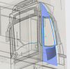
Now that I have a surface, adding the window is a little easier. As with the panel I use the drawing the sketch the outline of the window. I can then project this flat sketch onto the surface, so that it takes the shape of the panel. To make the window hole I just trim the surface around the sketch.

7.PNG

8.PNG

As I don't have a view looking down onto the body, I have had to get creative in how I built the front of the driver's cab. Using the side sketch and my original drawing plane, I plot points everywhere I can see a significant body panel joint. If I have missed any, I can jump back in at this stage and add them to the group.

9.PNG

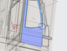
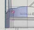
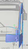
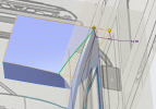
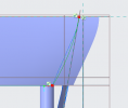
I then added an additional plane for the centreline of the tram. Looking head on I can add a point at the height I want the curve to end, such as the top of the nose valance circled in red. I then build a plane through this (red) point and parallel to the ground plane. If I find the point where the centreline, the point I placed earlier and the red point meet, I will know where the curve ends. By intersecting the outline of the side panel, and the new horizontal plane, I get the green point where the curve starts.

10.PNG

To get the rise on the front of the nose valance it is easier to build taller and cut back. A plain valance is build between two curves made from the process above. As with the window, I sketch out the shape of the bump of the nose and project it onto the valance. I can then trim the large surface back to the shape of the actual valance.

11.PNG

And that is where it stands for tonight :) All told, about 3 hours in so far, including sorting out my software and licences and sorting out the drawings. I moved from Design to Testing at work earlier in the year, so it took a little bit of time to find all the practices I've pushed to the back of my head :wondering: As mentioned above, a lot of time is spent going back and forth between CAD and photographs of the real thing. The trick comes in being able to break a complex shape down into lots of simple pieces, like if you were building and welding up body panels on a car.
 
  • Like
Reactions: 1 user

dunnyrail

DOGS, Garden Railways, Steam Trains, Jive Dancing,
Staff member
GSC Moderator
25 Oct 2009
26,171
4,993
75
St.Neots Cambridgeshire UK
Best answers
0
Country flag
It's worth noting at this point that when working on complex shapes like this I will work in what is referred to as 'surfaces'. Although the shapes exist in 3 dimensions, and can take on all the geometry of the outer skin of the final product, they have no thickness. This gives me more freedom to bend them to the required shape. Traditional 3d modeling involves drawing your 2D shape and then extruding it in a 3rd dimension.

Once I have the outline, I use a 'blend' to build a surface between the outlines. This is repeated for all of the panels I have drawn.

View attachment 271808

Now that I have a surface, adding the window is a little easier. As with the panel I use the drawing the sketch the outline of the window. I can then project this flat sketch onto the surface, so that it takes the shape of the panel. To make the window hole I just trim the surface around the sketch.

View attachment 271809

View attachment 271810

As I don't have a view looking down onto the body, I have had to get creative in how I built the front of the driver's cab. Using the side sketch and my original drawing plane, I plot points everywhere I can see a significant body panel joint. If I have missed any, I can jump back in at this stage and add them to the group.

View attachment 271811

I then added an additional plane for the centreline of the tram. Looking head on I can add a point at the height I want the curve to end, such as the top of the nose valance circled in red. I then build a plane through this (red) point and parallel to the ground plane. If I find the point where the centreline, the point I placed earlier and the red point meet, I will know where the curve ends. By intersecting the outline of the side panel, and the new horizontal plane, I get the green point where the curve starts.

View attachment 271812

To get the rise on the front of the nose valance it is easier to build taller and cut back. A plain valance is build between two curves made from the process above. As with the window, I sketch out the shape of the bump of the nose and project it onto the valance. I can then trim the large surface back to the shape of the actual valance.

View attachment 271813

And that is where it stands for tonight :) All told, about 3 hours in so far, including sorting out my software and licences and sorting out the drawings. I moved from Design to Testing at work earlier in the year, so it took a little bit of time to find all the practices I've pushed to the back of my head :wondering: As mentioned above, a lot of time is spent going back and forth between CAD and photographs of the real thing. The trick comes in being able to break a complex shape down into lots of simple pieces, like if you were building and welding up body panels on a car.
Wow I now know that this was not a project that I could have approached, I may have managed to cheat by using the Flexicity and trying to adapt that. However this will be something entirely different and I look forward to being able to get the prints done. Thanks again for your efforts.
 

musket the dog

Registered
31 Oct 2009
787
143
Leicester
nlrr.webs.com
Best answers
0
I did get a couple of hours in over the weekend, will update tonight :)
 

dunnyrail

DOGS, Garden Railways, Steam Trains, Jive Dancing,
Staff member
GSC Moderator
25 Oct 2009
26,171
4,993
75
St.Neots Cambridgeshire UK
Best answers
0
Country flag

dunnyrail

DOGS, Garden Railways, Steam Trains, Jive Dancing,
Staff member
GSC Moderator
25 Oct 2009
26,171
4,993
75
St.Neots Cambridgeshire UK
Best answers
0
Country flag
Till I have a few pics that may help. Will post them later.
435258BD-DE4A-459B-BA05-BA57DA902831.jpegC659463C-7C03-4989-8DA4-AD827CA1318A.jpeg47D84B3C-DEED-4B9F-87F0-8E2B4ABEB0A8.jpeg0E963211-0409-4097-BBC4-255C8B008009.jpeg
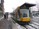
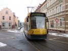
The following images are of the other Nordhausen Trams but as in the picture above I think thatbthey are pretty well identical so have posted the pics in case they are of help.
C596C23D-23BB-4C33-A7C5-98D39C78736E.jpeg
11AB955E-4422-40EC-956D-6CFCBEFCF0BF.jpeg

708D13C2-A1D0-4F79-AB5B-A91950AC4479.jpeg
 

Rhinochugger

Retired Oik
27 Oct 2009
36,716
4,240
North West Norfolk
Best answers
0
Country flag
Mmm - I don't think I'd make a model that you can only run in the winter :mask::mask::mask:
 

dunnyrail

DOGS, Garden Railways, Steam Trains, Jive Dancing,
Staff member
GSC Moderator
25 Oct 2009
26,171
4,993
75
St.Neots Cambridgeshire UK
Best answers
0
Country flag
Mmm - I don't think I'd make a model that you can only run in the winter :mask::mask::mask:
Aha just the only pice I have, not sure why I do not have bucket loads on one if my summer trips. Probably too interested in puffers and Harz Railcars.
 

musket the dog

Registered
31 Oct 2009
787
143
Leicester
nlrr.webs.com
Best answers
0
Evening all, a small update tonight that sums up about 2 hours work. In the progress I made here I probably went back and spent 30 - 45 minutes modifying or completely changing progress I had already made. Being practised at CAD design will allow you to construct your models in such a way that you can jump back in at an earlier point and pull lines around, or cut surfaces back and not have to reconstruct too many features after the fact. One of the benefits of making these mistakes in the computer instead of with materials is that nothing is wasted, just data. You might notice in the pictures that follow, lines and surfaces might jump around a bit. A lot of shapes and geometry on the prototype revealed itself after I had built it the first time.

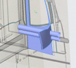
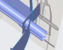
Picking up where we left off on the nose of the tram. A small detail in the prototype that stands out in the head on photos is the channel that runs through where the nose panels join. In the model I created this by extruding a C-section along the edge of the nose panel. I'll leave this as a separate floating piece until later. I've extended it past the ends slightly so that I can trim it back to the exact heights of the nose panel.

12.PNG

While I was working on the front end I added some place holders for the directional lights. These are quite simple; using the drawing I extrude two circles into cylinders so that they intersect the nose panel. As with the panel joint above, I'll leave these as they are for a while.

13.PNG 14.PNG

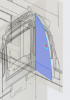
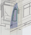
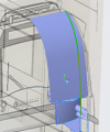
From the additional photos I had looked over I realised that there is in fact a 'flat' section running tangent with the windscreen. This is another extrude, created using the existing outside edge of the side panel. By using the edge, any changes I make to the side panel will be copied through to the front panel.

15.PNG

I then trim this back to the existing edge (you can only extrude and sketch onto flat surfaces or planes) and a line I've sketched from the drawing and projected onto the surface.

16.PNG

You might be able to notice that I change the surface created above quite a bit in the pictures below. One of the areas the drawings and the pictures of the prototype don't quite agree is the size and shape of this surface.
 
  • Like
Reactions: 1 user

musket the dog

Registered
31 Oct 2009
787
143
Leicester
nlrr.webs.com
Best answers
0
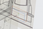
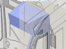
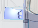
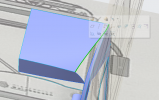
My next project was the destination board. I used the same processes of 2D sketches, intersected into 3D curves, placed using points anchored to the existing geometry to make the skeleton of the destination board box.

17.PNG

Once I had built the top surface, I could appreciate that the green edge highlighted hadn't come out quite the shape I was hoping for. I believe this is an effect of the two projections I have available to draw my sketches from.

18.PNG

To remedy this I start by extending the existing surface out past where I will need to trim it back to.

19.PNG

Looking down onto the surface, I can then draw a more suitable curve, and trim the new extended surface back to that.

20.PNG

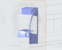
Another deviation I made from what I thought the drawing shows is to make the front of the destination board flat as I thought the photographs did not show the curve the drawings did. I think I've now seen some more pictures that show it is a different shape still, so I will come back later and modify it again. However I think I will still need the flat surface I have created here.

26.PNG
 
Last edited:
  • Like
Reactions: 1 user

musket the dog

Registered
31 Oct 2009
787
143
Leicester
nlrr.webs.com
Best answers
0
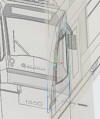
My final update for tonight is the 'Frenched' detail for the directional lights.

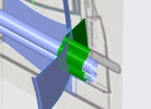
Using the two cylinders I made earlier I sketch out the shape of the recess for the lights and indicator on the rear plane and extrude that through the nose panel. Looking from the side, I extrude a surface from the edge of the side panel that crosses through the rest of the headlight geometry. The two new surfaces are highlighted green in the image below.

27.PNG

28.PNG

I can then merge these with the nose panel which also trims them all to the correct length at the same time.

29.PNG

The final step is to extrude what will become the small shelf on top of the nose, and fill in the gap left at the corner of the window frame. I will round off all of the sharp edges later.

30.PNG
 
  • Like
Reactions: 1 user

musket the dog

Registered
31 Oct 2009
787
143
Leicester
nlrr.webs.com
Best answers
0
The following images are of the other Nordhausen Trams but as in the picture above I think thatbthey are pretty well identical so have posted the pics in case they are of help.

Thank you for the additional pictures, some very useful angles in there that solved some of the questions I had regarding the geometry around the destination board especially :D
 

dunnyrail

DOGS, Garden Railways, Steam Trains, Jive Dancing,
Staff member
GSC Moderator
25 Oct 2009
26,171
4,993
75
St.Neots Cambridgeshire UK
Best answers
0
Country flag
Thank you for the additional pictures, some very useful angles in there that solved some of the questions I had regarding the geometry around the destination board especially :D
So glad I posted them, I look round some of my other trips to see if I have other. Not sure if the resulting pictures of some trips where I visited Nordhausen are all in my iPad. Love the work you are soing and can now begin to see the possibility of one of these superb Trams trundling around on my line and hopefully after all your work on some others lines as well.
 

musket the dog

Registered
31 Oct 2009
787
143
Leicester
nlrr.webs.com
Best answers
0
Just wanted to say this hasn't been forgotten about, I had a really busy week last week so hadn't made much progress but I have had the chance to put in a few of hours in the last couple of days :)
 
  • Like
Reactions: 1 user