Can you use an EPL Supplementary Switch 12030/12070 to switch a point/switch?

fairflixt

Vincent
27 Sep 2021
56
3
124
US
Best answers
0
Country flag
Hi all,

I'm a total newbie here and have been wiring up an automated alternating station circuit with signals (a combination of Circuit 5 and the Circuit Blocks on the World of LGB document). I need to at least move one of the switches/points to ensure the trains alternate/return to their spot in the station before sending the other one off. Is my only option to use more of the reed switches to send a signal to the point/switch to move or can I use all these open spaces on the DPDT switch to move things around? I have the reed switches so maybe that's easiest but through I'd ask in case there is another clever option.

In addition, I'm using an old 5003 power supply just for AC power to the EPL system. (On advice of this forum I did find a 5A throttle that I'm using combined with a Mean Well power supply.) It says it's 16VAC. In a number of threads on here it seems that 18VAC is recommended and possibly even using the booster box, 52750. I am seeing some sluggish movement on the signals I purchased used. Do those two extra volts really make a difference in more reliable movement? My understanding is still in it's infancy but I get the sense that buying an 18VAC power supply/transformer off Amazon would not plug and play, correct? I would need either an LGB part or to use some electronics to modify the AC power?

Thanks!
Vince
 

PhilP

G Scale, 7/8th's, Electronics
5 Jun 2013
33,566
3,521
Nottingham
Best answers
0
Country flag
To start at the back-end of your questions:
AC is AC.. - Anything else, is wobbly DC! ;)
If you are using an AC supply, then switching diodes to fire your points, etc. You will find that couple of volts, can make a difference. - It is a good 10% more.

If you have 'spare contacts, one-set on a double-pole switch, that are presently not connected, but will give you the control you want, then you should be able to use them, without any extra reed-switches.

PhilP
 

JimmyB

Now retired - trains and fishing
23 Feb 2018
6,948
921
69
Weston-super-Mare
www.tumble-down-falls.co.uk
Best answers
0
Country flag
I have in my hands a brand new 12010 Switch Drive, which is clearly labelled as DC 14 - 20 Volts. I operate my drives with 18V DC, and do not have an issue, these are of various ages including the old solenoid 3 terminal drives.
 

dunnyrail

DOGS, Garden Railways, Steam Trains, Jive Dancing,
Staff member
GSC Moderator
25 Oct 2009
26,171
4,993
75
St.Neots Cambridgeshire UK
Best answers
0
Country flag
Hi all,

I'm a total newbie here and have been wiring up an automated alternating station circuit with signals (a combination of Circuit 5 and the Circuit Blocks on the World of LGB document). I need to at least move one of the switches/points to ensure the trains alternate/return to their spot in the station before sending the other one off. Is my only option to use more of the reed switches to send a signal to the point/switch to move or can I use all these open spaces on the DPDT switch to move things around? I have the reed switches so maybe that's easiest but through I'd ask in case there is another clever option.

In addition, I'm using an old 5003 power supply just for AC power to the EPL system. (On advice of this forum I did find a 5A throttle that I'm using combined with a Mean Well power supply.) It says it's 16VAC. In a number of threads on here it seems that 18VAC is recommended and possibly even using the booster box, 52750. I am seeing some sluggish movement on the signals I purchased used. Do those two extra volts really make a difference in more reliable movement? My understanding is still in it's infancy but I get the sense that buying an 18VAC power supply/transformer off Amazon would not plug and play, correct? I would need either an LGB part or to use some electronics to modify the AC power?

Thanks!
Vince
Not sure if this will help but the trains are moved from isolating places by lgb point mootirs with axiliary switches. A further sensor or two on the right would have enabled the trains to alternatively use the right hand loops by changing the point by each train. A plan but not yet done as the auto line not been used for a few years.
 

fairflixt

Vincent
27 Sep 2021
56
3
124
US
Best answers
0
Country flag
To start at the back-end of your questions:
AC is AC.. - Anything else, is wobbly DC! ;)
If you are using an AC supply, then switching diodes to fire your points, etc. You will find that couple of volts, can make a difference. - It is a good 10% more.

If you have 'spare contacts, one-set on a double-pole switch, that are presently not connected, but will give you the control you want, then you should be able to use them, without any extra reed-switches.

PhilP

Hi Phil,

Thanks for the reply. You are right that I should probably learn the terminology better! So, just to be clear, I'm powering my points with the 3/4 connections from this transformer. You'll see that it is labeled as 16VAC with 7VA. There are no additional diodes or anything that I have installed. The connections go directly to the points. Based on some of the other threads on this forum that I've read, I was thinking that the points operate on a polarity shift which means they actually run on DC (or wobbly DC, i.e. half wave rectified AC). Thus I'm confused since my transformer is calling it AC and now I'm wondering if it's actually the half wave rectified AC that's coming out there. Is there some way to measure that with a multimeter?

On reading further around here and the internet, there does seem to be a concern around the DPDT making a continuous connection, i.e. supplying voltage to the point continuously. Presumably this is bad for the point motor vs. the momentary switches, like on the LGB switching box, that sends a short signal pulse. If I understand correctly it would result in something like the point motor always pushing in one direction . Do I understand that correctly? If so, then I guess you would need to add something like a momentary switch as a way to limit the time the signal is sent?

Cheers,
Vince

Edit: I forgot to add good point on the 10% more, when put that way it does make sense to maybe look for something with a little more oomph!
 

fairflixt

Vincent
27 Sep 2021
56
3
124
US
Best answers
0
Country flag
I have in my hands a brand new 12010 Switch Drive, which is clearly labelled as DC 14 - 20 Volts. I operate my drives with 18V DC, and do not have an issue, these are of various ages including the old solenoid 3 terminal drives.
So if I procured an 18V DC transformer then I wouldn't need the transformer from my original starter set at all, would get the extra voltage boost and could get something that could hand 2+ amps in case I want to reliably switch multiple points at the same time, correct?
 

fairflixt

Vincent
27 Sep 2021
56
3
124
US
Best answers
0
Country flag
Not sure if this will help but the trains are moved from isolating places by lgb point mootirs with axiliary switches. A further sensor or two on the right would have enabled the trains to alternatively use the right hand loops by changing the point by each train. A plan but not yet done as the auto line not been used for a few years.
Hi - I'm sorry, I'm a bit confused, are you refering to your garden railroad layout as an example? Or is it a suggestion for my design?
 

PhilP

G Scale, 7/8th's, Electronics
5 Jun 2013
33,566
3,521
Nottingham
Best answers
0
Country flag
Hi Vince,

You are correct, the point motors need DC to operate, and the polarity decides which way they are thrown.
If you are using AC, then you can use a single-pole centre-off switch, and two diodes to give you the 'lumpy' half-wave negative or positive DC to operate your turnouts.
If you are using pure DC, then you need a centre-off double-pole switch, as the switch has to give either negative or positive supply to the motor.

Yes, either way, it should be a momentary switch, which snaps back to a centre-off position.

The auxiliary switches on the turnout motors, are either 'on' or 'off', and not momentary, so you would need additional circuitry, if you wanted an auxiliary switch to fire a turnout.

One way to do this, would be to route the power for the turnout through its own auxiliary switch..
This would have to be a closed contact, so that when the turnout operated, it was then opened, so cutting power to itself. - A higher voltage (for a bigger initial 'kick') would be useful.

PhilP
 

korm kormsen

Registered
24 Oct 2009
2,765
296
Country
Paraguay
Best answers
0
Country flag
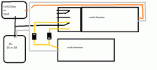
you might try this:

switch-switching.gif
:confused: Edit: nooo, don't do that! the secondary switchmotor would run all the time!
(i did not find a way to delete the entire post)
 
Last edited:
  • Haha
Reactions: 1 user

fairflixt

Vincent
27 Sep 2021
56
3
124
US
Best answers
0
Country flag
I have in my hands a brand new 12010 Switch Drive, which is clearly labelled as DC 14 - 20 Volts. I operate my drives with 18V DC, and do not have an issue, these are of various ages including the old solenoid 3 terminal drives.
Hi Jimmy - does this mean you also have the 18V DC going to reed switches/track contacts (like LGB 17100)? Assuming you use those at all. I can't seem to find any documentation indicating their technical specs. and if they have the same voltage range as the switch drives.
 

fairflixt

Vincent
27 Sep 2021
56
3
124
US
Best answers
0
Country flag
Hi Vince,

You are correct, the point motors need DC to operate, and the polarity decides which way they are thrown.
If you are using AC, then you can use a single-pole centre-off switch, and two diodes to give you the 'lumpy' half-wave negative or positive DC to operate your turnouts.
If you are using pure DC, then you need a centre-off double-pole switch, as the switch has to give either negative or positive supply to the motor.

Yes, either way, it should be a momentary switch, which snaps back to a centre-off position.

The auxiliary switches on the turnout motors, are either 'on' or 'off', and not momentary, so you would need additional circuitry, if you wanted an auxiliary switch to fire a turnout.

One way to do this, would be to route the power for the turnout through its own auxiliary switch..
This would have to be a closed contact, so that when the turnout operated, it was then opened, so cutting power to itself. - A higher voltage (for a bigger initial 'kick') would be useful.

PhilP
Thanks Phil,

So yes, it is technically possible, but you can't just connect the auxiliary switch but need some additional component to ensure you aren't sending a continuous signal to the point. This seems more complicated than using a few more track contacts to throw the switch/point as needed.

Thanks for the helpful discussion and information!

Vince
 

JimmyB

Now retired - trains and fishing
23 Feb 2018
6,948
921
69
Weston-super-Mare
www.tumble-down-falls.co.uk
Best answers
0
Country flag
Hi Jimmy - does this mean you also have the 18V DC going to reed switches/track contacts (like LGB 17100)? Assuming you use those at all. I can't seem to find any documentation indicating their technical specs. and if they have the same voltage range as the switch drives.
No reed switches, just a Revolution TE controlling my switches (points).
 

dunnyrail

DOGS, Garden Railways, Steam Trains, Jive Dancing,
Staff member
GSC Moderator
25 Oct 2009
26,171
4,993
75
St.Neots Cambridgeshire UK
Best answers
0
Country flag
Hi - I'm sorry, I'm a bit confused, are you refering to your garden railroad layout as an example? Or is it a suggestion for my design?
No sorry if I confused, it is a small portable layout that I thought may give you ideas of how LGB can be automated.
 

PhilP

G Scale, 7/8th's, Electronics
5 Jun 2013
33,566
3,521
Nottingham
Best answers
0
Country flag
No sorry if I confused, it is a small portable layout that I thought may give you ideas of how LGB can be automated.
Jon,
There was no image, or link, in your post.. I think it was that which caused the confusion?

PhilP
 

dunnyrail

DOGS, Garden Railways, Steam Trains, Jive Dancing,
Staff member
GSC Moderator
25 Oct 2009
26,171
4,993
75
St.Neots Cambridgeshire UK
Best answers
0
Country flag
Jon,
There was no image, or link, in your post.. I think it was that which caused the confusion?

PhilP
Hi - I'm sorry, I'm a bit confused, are you refering to your garden railroad layout as an example? Or is it a suggestion for my design?
Oh dear so sorry forgot to click in the link. I get so tied in to my drivel that I end up posting and forgetting tompost the link. Hooe your confusion is a little bit reduced now! Must remember to post any link then rabit away!

 
  • Like
Reactions: 1 user

fairflixt

Vincent
27 Sep 2021
56
3
124
US
Best answers
0
Country flag
Oh dear so sorry forgot to click in the link. I get so tied in to my drivel that I end up posting and forgetting tompost the link. Hooe your confusion is a little bit reduced now! Must remember to post any link then rabit away!

Now I follow get your text! Thanks for the example, this was helpful.
 

fairflixt

Vincent
27 Sep 2021
56
3
124
US
Best answers
0
Country flag
For what it's worth to anyone who ends up reading this thread in the future, here is a sketch of how the AC signal is converted either by the momentary switch box or the reed contacts (as per the descriptions above it's not a surprise that the secret sauce is diodes!). Unfortunately, the text is in German but the pictures are useful. The World of LGB manual/guide actually has a good description of the EPL system as well. I had read it before but it clearly didn't sink in until I was asking about things in this thread.


1634098138121.png

1634098252805.png