Bringing the AA20 (Andrey Andreev 20 ton per axle) back to life...4-14-4

justme igor

Registered
17 Apr 2020
679
64
Netherlands Westwoud
Country
Netherlands
Best answers
0
Country flag
I granted/treaded/spoiled myself a day for the aa20, but aldo the thing(frame) is driving on my track i have a question.
The RUFF outside dimensions are somewhat /~clear\???? to me, yes i am into a 0.1 of a mm.

Those stars? above the fire box what are they and can some one provide please a better picture if there is such a picture of something looking simulair?
The one and only video of the AA20 is not sharp enough to go into detail, i hope you all know what part i am referring to and what it does and a clear picture of something simulair.
(hold something in place? parts of the firebox??double wall fire box???no?)
vuurkist.png
better picture wnted.png
You will see 7 of those "stars/rings" behind the sand dome lines on the kettle.
What are they and if there is a better "look a like" picture i would really appreciate to have it for better detail.
Thanks in advance
With best regards Igor

Btw that thing is a beast.... an animal...its big, long and high....To heavy and to big for those tracks back then...Yes i have the dimensions complete.
 

dunnyrail

DOGS, Garden Railways, Steam Trains, Jive Dancing,
Staff member
GSC Moderator
25 Oct 2009
26,166
4,991
75
St.Neots Cambridgeshire UK
Best answers
0
Country flag
I granted/treaded/spoiled myself a day for the aa20, but aldo the thing(frame) is driving on my track i have a question.
The RUFF outside dimensions are somewhat /~clear\???? to me, yes i am into a 0.1 of a mm.

Those stars? above the fire box what are they and can some one provide please a better picture if there is such a picture of something looking simulair?
The one and only video of the AA20 is not sharp enough to go into detail, i hope you all know what part i am referring to and what it does and a clear picture of something simulair.
(hold something in place? parts of the firebox??double wall fire box???no?)
View attachment 291920
View attachment 291919
You will see 7 of those "stars/rings" behind the sand dome lines on the kettle.
What are they and if there is a better "look a like" picture i would really appreciate to have it for better detail.
Thanks in advance
With best regards Igor

Btw that thing is a beast.... an animal...its big, long and high....To heavy and to big for those tracks back then...Yes i have the dimensions complete.
Boiler washout plugs, these are removed so that lines can be placed for water to wash out the boiler.
 

justme igor

Registered
17 Apr 2020
679
64
Netherlands Westwoud
Country
Netherlands
Best answers
0
Country flag
thanks dunnyrail.
Different problem or i am seeing ghosts:
We all know that there where build two of them.
Judging by the pictures(detail) there is a different loco at the scrap yard(1965) then the loco in the promo video(1935)
1.png
This one is from the scrap yard from 1965


2.png
3.png
Those two are from the original video.
In both pictures you can see that the "letters" are welded on, but on the scrap yard picture there is no evidence or what so ever that it was there...
I noticed also some weird differences in the front...
I really think we are looking on two different loco's
There is also a big differences between there sand boxes.
I think the one in the scrap yard is the number two, especially if you look at the windows, letters on the cabin and the return steam pipes into the asbox? thingy below the chimney(that room)
So the number one is/was converted to a DB 6 wheeler.
I know for almost sure one of those loco's was converted for the DR....

With best regards
Igor
 

justme igor

Registered
17 Apr 2020
679
64
Netherlands Westwoud
Country
Netherlands
Best answers
0
Country flag
it is getting some shape.

20211107_173314.jpg
20211107_173303.jpg
20211106_161504.jpg
Yes there is one wheel missing, i cN NOT BUY the tread i would like...yet....m2

But also a bit of fun i dusted off the terrier loco.
Dont mind those two wooden baring pivoting points! in that picture!

Now lets get serious where do i cut the frame?
There are 2 wooden supports, those would be my choose.
Obvious the wooden block under the cabin must be shifted a bit more into the front....
Any advice even from Greg would be appreciated( i know you are following me)...

I would not like to cut the frame in the middle due to traction and baring loss.
I can melt lead in any form you want, but cuting the frame in half....
In the first two pictures the fire box is in its place, but not MY pivoting point.
It will go on a 4.5 metre radii in this wheel set, but the front runners or the back support bogie...where do i cut the frame.
It was a ONE whole frame loco, even thos seven driving wheels had some clearance, in model impossible.

Thanks in advance, best igor
 

Paul M

Registered
25 Oct 2016
11,881
1,696
60
Royston
Best answers
0
Country flag
Now lets get serious where do i cut the frame?
I would suggest between every other wheel, that would enable it to go round most things. BUT I also think that would be a very difficult task
 

PhilP

G Scale, 7/8th's, Electronics
5 Jun 2013
33,561
3,521
Nottingham
Best answers
0
Country flag
Without seeing how it doesn't go round corners, or knowing what will be hanging down below the footplate, around the trucks and drivers, it is very difficult to make sensible suggestions...

I think I would look to the likes of LGB, and their Harz 2-10-2, for inspiration?
They are, after all, the 'de-facto' experts, on long wheelbase and tight radius.

PhilP
 

dunnyrail

DOGS, Garden Railways, Steam Trains, Jive Dancing,
Staff member
GSC Moderator
25 Oct 2009
26,166
4,991
75
St.Neots Cambridgeshire UK
Best answers
0
Country flag
it is getting some shape.

View attachment 292066
View attachment 292067
View attachment 292068
Yes there is one wheel missing, i cN NOT BUY the tread i would like...yet....m2

But also a bit of fun i dusted off the terrier loco.
Dont mind those two wooden baring pivoting points! in that picture!

Now lets get serious where do i cut the frame?
There are 2 wooden supports, those would be my choose.
Obvious the wooden block under the cabin must be shifted a bit more into the front....
Any advice even from Greg would be appreciated( i know you are following me)...

I would not like to cut the frame in the middle due to traction and baring loss.
I can melt lead in any form you want, but cuting the frame in half....
In the first two pictures the fire box is in its place, but not MY pivoting point.
It will go on a 4.5 metre radii in this wheel set, but the front runners or the back support bogie...where do i cut the frame.
It was a ONE whole frame loco, even thos seven driving wheels had some clearance, in model impossible.

Thanks in advance, best igor
Clearly you need to do similar to LGB, the 2-10-2 is 3 axles 2axles between the split. Thus with your loco you would need to cut split 4 axles 3 axles.
 
8 Mar 2014
7,806
972
San Diego
Country
Armenia
www.elmassian.com
Best answers
0
Country flag
I cannot see how the question can be answered without knowing minimum curvature it is being designed for.

At that point, overhang could be simulated and the visual aspect could also be considered.

Greg
 

justme igor

Registered
17 Apr 2020
679
64
Netherlands Westwoud
Country
Netherlands
Best answers
0
Country flag
I would suggest between every other wheel, that would enable it to go round most things. BUT I also think that would be a very difficult task
That was my first intention, to create a chain like frame, and put the electric engines in the tender.
However if this is going to be the "proto type" for my steam build i would have a problem with the weight distribution and also traction power.
I also considered to cut the frame up into pieces that will accommodate the first 2 wheels, 3 wheels(unflanged) and a section for the last 2 driving wheels.
The front runners and the rear support are capable of carring the weight of the boiler, but not enough traction to get a big number of wagons moving.

I think I would look to the likes of LGB, and their Harz 2-10-2, for inspiration?
They are, after all, the 'de-facto' experts, on long wheelbase and tight radius.
Nice looking loco, but i could not find any specs of the wheelbase on how they constructed it.

I cannot see how the question can be answered without knowing minimum curvature it is being designed for.

At that point, overhang could be simulated and the visual aspect could also be considered.

Yes Greg, thank you for your replay, i made some pictures in the hope to get it more clear.
It was not easy to get some good pictures.
20211108_074928.jpg
20211108_074851.jpg

What you see is a 4 meter/13.12 foot radii curve, i am designing the aa for this curve so it will go better around 4.5 and a 5 meter radii curve.
Below that curve is a strait piece of track.
The aluminium housing is basically the total length of the loco minus 2.5 cm/1 inch for the bumpers.

20211108_080937.jpg

I can flip the second motor so i can create a 3 1 3 wheelbase, but this option is not really my wish for reasons with weight distribution/traction.
Btw as you stated before i still must make the wheels thicker and the flange a bit higher.
But surprisingly it runs happy on a 4.5 meter radii curve.

Where to cut? yes, you all know i overthink to much.

20211108_081559.jpg

I think the best option is number 2.
The red circles are the support for the boiler, the circle with the "x" is for the wires atm.

Thanks in advance, with best regards Igor
 
8 Mar 2014
7,806
972
San Diego
Country
Armenia
www.elmassian.com
Best answers
0
Country flag
OK, great, you know I am a step by step guy.

So 4 meter radius is ok.

I would certainly design for this large radius rather than chop it up to handle something much smaller. I do not follow the LGB philosophy of making large locos take ridiculously sharp, toy like curves.
too_sharp.jpg


So I would go for the minimum of "pieces" of the frame. This will also be important when you do the rod gear, since the fewer "hinge points" the easier it will be to make the side rods. You will need to have to figure out how to add this flexibility, but making it easier to solve is good.

I would consider that there are 2 "driver modules" of 3 axles each. and the "central" driver would be unpowered and the 2 modules would hinge to it using a short "frame piece" that is just long enough to have the driver journals and the hinge points for your two "3 axle modules".

Then perhaps the boiler would be fixed to this central short module, and then a sliding plate in the top center of each 3 axle module. This way the weight of the boiler would be evenly distributed between the 2 modules, and the weight also evenly distributed between the 3 axles of each module.

I think this would also minimize locomotive overhang.

This is where I would start. Doing this I would not make any blind drivers, all flanged.

Greg
 
  • Like
Reactions: 1 user

justme igor

Registered
17 Apr 2020
679
64
Netherlands Westwoud
Country
Netherlands
Best answers
0
Country flag
20211109_180834.jpg
20211109_181110.jpg
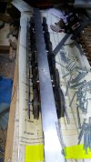
If tools are to expensive make your own, yes finally got my metal screws in different sizes.

20211109_180806.jpg
20211109_180904.jpg


To bad i can not post a video or a gif:
20211109_182509.jpg


Greg Elmassian Greg Elmassian
Thank you for your reply
Now with that picture you posted is not what i want, that is the opposite.
I found some youtube videos with that kind of "overhang" incl the big boy, sorry no...nightmare fuel, really NOT what i want.
I would like to have my aa20 as natural as it is, and i am close.
Did several experiments of what i would like and the pivoting points i mention earlier are probably the best, but the one on the back (for the wires)must be further back, more to the tender.
But oke lets do it your way: step by step, aldo i have something it is ONE machine.
But a machine has several parts that needs attention, but one can not function without the other

You mentioned the "side rods"those things that are connecting the driver wheels.
For NOW i have them attached all to each other on one unhinged strip.
It will "go" on a 4 meter radii curve, bingo!(4.5 is better performance and 5 meter radii is flawless)
The rods will have some hinged parts so that the drivers will have there 1.5mm clearance instead of being restrained with the single unhinged rod...\
20211109_181850.jpg

When i have time i will make it like the real thing:
The unflanged wheels will have one solid rod connected with a hings to the next wheel and connect with a other hinge to the most outer wheel.
So this will give me more accurate aproge to scale modelling. instead of a gauge of 42mm i can go to probably 44mm gauge(important for frogs)
But this aside:
Schermafbeelding 2021-11-09 193210.png
Schermafbeelding 2021-11-09 201401.png

You see here the last 3 wheels, all 3 clearly hinged, the same applies for the first three.
But the middle three are connected with one solid rod powered by the cylinder in the middle.
This will give me a 2 -3 mm extra on gauge

Back to a other idea of you, that approach the reality in 1935 and what i wanted to do.
In the video's and original pictures you clearly see FOUR plates in the middle of the boiler that are supporting some of the weight of the boiler on the frame...
After looking at some artikels again i believe that there where indeed sliding, just like the front runners and the back support.
Even in model if i want a true look/appearance, i must built it this way...
It is hard to see but in the slow mo with the video you can see those four.
Schermafbeelding 2021-11-09 201712.png
53153135135.jpg

So I would go for the minimum of "pieces" of the frame. This will also be important when you do the rod gear, since the fewer "hinge points" the easier it will be to make the side rods. You will need to have to figure out how to add this flexibility, but making it easier to solve is good.
So it can be my option two(my paper drawing), but preferably no cuts, but the struggle of the support of the boiler with the the front runners and the back support that they can shift/move sideways under the main frame.
That the middle part of the boiler will shift left and right a bit (an inch from the centre of the track in scale).
Back to the rods, they will be all as they designed it back than, i have no choice left....

I would consider that there are 2 "driver modules" of 3 axles each. and the "central" driver would be unpowered and the 2 modules would hinge to it using a short "frame piece" that is just long enough to have the driver journals and the hinge points for your two "3 axle modules".
I dont think this is nececery, and that it can be done with one frame, i will go experiment with your first idea (like this one the most) and report back...btw the middle/central driver is unpowered

Shit.... why couldn't i find a easier to make and a good looking model....like the red devil or the DR 59 501 or...


With best regards Igor

ps "rod gear" witch one is that exactly? the one needed for speed and reverse?
Ps2 the wheels are still from abs plastic, when i figured out everything i will start casting them in zamac for live steam incl cnc and lathe in a different topic, this is just a learning curve and to get it all right before the exam.
 

Attachments

  • 20211109_181906.jpg
    20211109_181906.jpg
    243.3 KB · Views: 0

PhilP

G Scale, 7/8th's, Electronics
5 Jun 2013
33,561
3,521
Nottingham
Best answers
0
Country flag
'Rod gear'
I think you are referring to :
UK Reverser
US Johnson bar

Used for 'notching-up' - altering the valve-timing and reverse/forward.

(I do hope that I have that correct).

PhilP
 
8 Mar 2014
7,806
972
San Diego
Country
Armenia
www.elmassian.com
Best answers
0
Country flag
So, I have a small amount of confusion on all your replies, but I think you said you like my original idea not to hinge the frame, but hinge the side rods as necessary.

Your pictures seem to show this is possible.

Just let me know I am on the right "track" ;)

Greg
 

justme igor

Registered
17 Apr 2020
679
64
Netherlands Westwoud
Country
Netherlands
Best answers
0
Country flag
but I think you said you like my original idea not to hinge the frame, but hinge the side rods as necessary.

Your pictures seem to show this is possible.
Yes.
It was in the planning to hinge the side rods, this will give me some extra side to side movement between the tracks.
The wheels are now on one fixed side rod to see what she will do on a 4 meter radii curve.
The wheels are 42mm gauge instead of 45mm
With hinged side rods she can move more easy on 4 meter and bigger curves due to the extra movement/side clearance in the axles/frame/wheelbase.

As the real thing:
sid rod hinges.png

The situation that i have now is only the yellow bar, very little side to side movement, 1 mm

Between every red and green side rod there is a sliding/shifting bearing with also "knee" movement.
Between every red and black side rod is a hinge.
The connection between the two green bars is also a "knee" movement.(connected to the middle driver wheel)
The long red rod is fixed for one movement: in and out of the cylinder with two attachments on the frame.
This can give me(i hope) 2mm per side more side to side movement.

This will make the wheel follow the track more natural and the boiler more natural look on the frame without overhang?
So the boiler will shift/hover on the middle of the frame.
But i think i must hinge the back support(rear boogie?) for the tender to follow more natural.
And the boiler support must be above/ in between the cylinders and the last driving wheels.(model)
Also to keep balance about the centre of gravatie

I believe the boiler support was fully (on the real AA20) on the back support(also in the name)
That is why i am really reluctant to cut up the frame, when i am going to built her in live steam we are not talking anymore about the weight of thin pvc pipe and some air.
So the weight of the boiler in the back is giving me some challenges and the following of the tender, connection between the cab and tender that is.
The third and i think the most important boiler support is the standing sliding sheets in the middle of the boiler on top of the frame.

To sum the problems up:
Overhang in the middle that the centre of gravity will be to high.
The overhang in the middle will look really bad.
Connection and following between the tender and the cab.
Side to side movement of the wheels must be good for a 4 meter radii curve.(axles must have some clearance too to move back and forward instead of only side to side)
Weight distribution on a cut up/hinged frame for traction wise is a very bad idea.

The answer is probably somewhere on the back support.

So, I have a small amount of confusion on all your replies
I hope some of the confusion is taking away now?
If not let me know.

With best regards Igor


***joke***
It would be nice to have it coal powered, but to make a mechanical feeder?
 
8 Mar 2014
7,806
972
San Diego
Country
Armenia
www.elmassian.com
Best answers
0
Country flag
Yes, I understand better. What I have seen of long boiler locomotives is to minimize overhang at rear, it appears to cause more problems with trailing truck.

(by the way, the conventions I understand here is pilot or leading truck... then drivers, then trailing truck)

So I think your statement "But i think i must hinge the back support(rear boogie?) for the tender to follow more natural." is about the trailing truck?

I am striving to make sure we have the same basic terms, so can you confirm again that I am understanding you correctly?

Greg
 

justme igor

Registered
17 Apr 2020
679
64
Netherlands Westwoud
Country
Netherlands
Best answers
0
Country flag
'Rod gear'
I think you are referring to :
UK Reverser
US Johnson bar

Used for 'notching-up' - altering the valve-timing and reverse/forward.

(I do hope that I have that correct).
NL + Belgium (and in German i think):

I knew i had a good picture of the middle boiler support:
mid bioler support.png

Just out of curiosity what are those two drum like shaped things on top of the frame?
 

justme igor

Registered
17 Apr 2020
679
64
Netherlands Westwoud
Country
Netherlands
Best answers
0
Country flag
(by the way, the conventions I understand here is pilot or leading truck... then drivers, then trailing truck)

So I think your statement "But i think i must hinge the back support(rear boogie?) for the tender to follow more natural." is about the trailing truck?

I am striving to make sure we have the same basic terms, so can you confirm again that I am understanding you correctly?
yes trailing truck
 
8 Mar 2014
7,806
972
San Diego
Country
Armenia
www.elmassian.com
Best answers
0
Country flag
So you are concerned that the trailing truck might have problems and you should consider a moving last driver?

I think I see what you are asking, but the alignment of the trailing truck is usually visually centered under the end of the loco, the idea was to help support the weight of the firebox I believe.

I think you can come up with a pivoting scheme to keep the trailing truck looking better centered under the cab and firebox without having the last driver "flex" or pivot. I really like the idea of keeping the frame all one piece.

To accommodate this you have:
  • narrowed the wheel gauge
  • selected a large track curvature/radius
  • eliminated switches/turnouts (for now)
  • given some play between the main rod(s) and the wheels
  • looking to hinge various points in the side rods
  • (not sure on this) added side to side play in the drivers themselves (maybe you cannot achieve this with the chosen gearboxes)
So far I think you can achieve it. It seems that now your main concern is visual, the overhang (ends and middle) of the boiler.

I like it.

Greg
 
Last edited:
  • Like
Reactions: 1 user