justme igor
Registered
I think this is the right section of the forum?
. . . . . . . ........... Total hours (re)designing: 108
. . . . . . ............. Total hours printing: 45
. . . . . ................ Total hours of tinkering: 8
I finally started with designing and building the AA20.
I thought it would be nice to share this build from the first hour to the first meter of driving.
There will be 2 versions made, both will be prototypical 100% correct.
1 will be 3d printed with all the accurate details.
2 will be a live steam one.
I need to make the files anyway to make/create for the casting.
The live steam loco will be a follow up or a different topic.
It is in scale 1/32 a whooping 1 meter 5 cm and 4 mm or for those imperial 41,49 inch from coupler to coupler
I really dont know what the smallest radii she must have, but i guess 3 meters minimum, my biggest curve is 4 meters, wish me luck on this one.
I just completed the housing for the engine, the first print will be in pla incl the wheels.
If the whole thing will drive on a certain curve I will make her in abs.
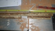
In the pictures on the key board you will see a (~failed) experiment, but it will give a impression of what this is all going about.

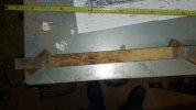
View inside the moterhome/motor house.

Disassembled ready for pins and glue after the motors are fitted and soldered.

A ruff total view to give a impression.
Sinds i suspect this is going to be a long thread and to keep it a bit clean i will place my updates in this first message.
I hope you will enjoy and appreciate that i am sharing this project.
There where just 3 others before me that completed this loco 1 for selling btw
Update as 9 feb 2021,Update as 9 feb 2021
As you can see i had to redesign the motor home, it was just to short for the electro motors


For the front support i had to make up a sort of connection, my printer bed is just not long enough in diagonal.
Sinds this is also a rigged frame this brings in some very mechanical challenges, i am having fun.
The front boogie is going to be attached to the upper frame and will get a left right guidance.
This will be probably need lithium grease.
Sinds the front of the boiler is also resting with his weight it must have a smooth bearing surface
The rear support will get probably the same construction for distribution of its weight, but will be connected as a trailer.
Even in abs with some electronics, motors and li ion cells, i think this will be a heavy one.
Good for the traction
The bottom side of the motor house is now printing.
Experimental in pla.
I finished all the wheels:


I printed the first and the third wheel a couple of times and mounted them on the test frame.


The test wheels were ~satisfactory....pla is not my material and the printer is fine tuned for abs....
In the test setup all went oke but the drive not so well.
Between the rail and the flange i have just 0,5mm clearance, total of 1mm, works very good for small locos and cars, but not for bigger sizes.
The wheel/drive shaft connector will be a 0,5mm shorter, i can go to 1mm before i will get trouble with my frogs, probally going to widen them from 2.2 mm 30mm....
That kind of clearance is doable with prototypical correct....
With best regards Igor
Update as per 14-feb-2021

Almost forgot the fun of soldering...

Not really happy:

Some wheels are missing.

Problem to get the axles presses into the axle holders and wheels, will figure this out

This is going to be big....
.
.
.
For Greg:
Yes i use prototypical and g1mra specs:

This can work

Ofcourse this wont work......

Will do greg....it will do
Sorry i did not post earlier, i was real pretty really busy...making snowman, throwing snowballs, acting like a teenager again, but having a own company?!?!?!?!......sipping brandy and quality wiskey (macallan 30 yr i can recommend!)by the fireplace, walking dogs in the snow...those kind of things busy.....
Till so far my lies and deception...This was my progress on the AA20 so far, any comment, thought or idea is welcome.
It is one stubborn B......
She will not go over 3 meter radii curves, the reason why it was one big failure is coming floating above water....

Even reducing the width to 41mm flange to flange is not helping to take a 3 meter radii, and this is not even with the front or back support!

This is with thin wheels, i will try wheels with 7mm instead of 5mm thickness.....
Keep it prototypical....I tried curves with a raddi of 4 meter...~that ~goes ~well....big bed sheeeeeet
I can not add more than 20 pictures... i will proceed in a other post, sorry
With best regards Igor
. . . . . . . ........... Total hours (re)designing: 108
. . . . . . ............. Total hours printing: 45
. . . . . ................ Total hours of tinkering: 8
I finally started with designing and building the AA20.
I thought it would be nice to share this build from the first hour to the first meter of driving.
There will be 2 versions made, both will be prototypical 100% correct.
1 will be 3d printed with all the accurate details.
2 will be a live steam one.
I need to make the files anyway to make/create for the casting.
The live steam loco will be a follow up or a different topic.
It is in scale 1/32 a whooping 1 meter 5 cm and 4 mm or for those imperial 41,49 inch from coupler to coupler
I really dont know what the smallest radii she must have, but i guess 3 meters minimum, my biggest curve is 4 meters, wish me luck on this one.
I just completed the housing for the engine, the first print will be in pla incl the wheels.
If the whole thing will drive on a certain curve I will make her in abs.
In the pictures on the key board you will see a (~failed) experiment, but it will give a impression of what this is all going about.
View inside the moterhome/motor house.
Disassembled ready for pins and glue after the motors are fitted and soldered.
A ruff total view to give a impression.
Sinds i suspect this is going to be a long thread and to keep it a bit clean i will place my updates in this first message.
I hope you will enjoy and appreciate that i am sharing this project.
There where just 3 others before me that completed this loco 1 for selling btw
Update as 9 feb 2021,Update as 9 feb 2021
As you can see i had to redesign the motor home, it was just to short for the electro motors
For the front support i had to make up a sort of connection, my printer bed is just not long enough in diagonal.
Sinds this is also a rigged frame this brings in some very mechanical challenges, i am having fun.
The front boogie is going to be attached to the upper frame and will get a left right guidance.
This will be probably need lithium grease.
Sinds the front of the boiler is also resting with his weight it must have a smooth bearing surface
The rear support will get probably the same construction for distribution of its weight, but will be connected as a trailer.
Even in abs with some electronics, motors and li ion cells, i think this will be a heavy one.
Good for the traction
The bottom side of the motor house is now printing.
Experimental in pla.
I finished all the wheels:
I printed the first and the third wheel a couple of times and mounted them on the test frame.
The test wheels were ~satisfactory....pla is not my material and the printer is fine tuned for abs....
In the test setup all went oke but the drive not so well.
Between the rail and the flange i have just 0,5mm clearance, total of 1mm, works very good for small locos and cars, but not for bigger sizes.
The wheel/drive shaft connector will be a 0,5mm shorter, i can go to 1mm before i will get trouble with my frogs, probally going to widen them from 2.2 mm 30mm....
That kind of clearance is doable with prototypical correct....
With best regards Igor
Update as per 14-feb-2021
Almost forgot the fun of soldering...
Not really happy:
Some wheels are missing.
Problem to get the axles presses into the axle holders and wheels, will figure this out
This is going to be big....
.
.
.
For Greg:
Yes i use prototypical and g1mra specs:
This can work
Ofcourse this wont work......
Will do greg....it will do
Sorry i did not post earlier, i was real pretty really busy...making snowman, throwing snowballs, acting like a teenager again, but having a own company?!?!?!?!......sipping brandy and quality wiskey (macallan 30 yr i can recommend!)by the fireplace, walking dogs in the snow...those kind of things busy.....
Till so far my lies and deception...This was my progress on the AA20 so far, any comment, thought or idea is welcome.
It is one stubborn B......
She will not go over 3 meter radii curves, the reason why it was one big failure is coming floating above water....
Even reducing the width to 41mm flange to flange is not helping to take a 3 meter radii, and this is not even with the front or back support!
This is with thin wheels, i will try wheels with 7mm instead of 5mm thickness.....
Keep it prototypical....I tried curves with a raddi of 4 meter...~that ~goes ~well....big bed sheeeeeet
I can not add more than 20 pictures... i will proceed in a other post, sorry
With best regards Igor
Last edited: