Rhinochugger
Retired Oik
There is a way of achieving a single curved span, but it'll take some work and some thinking out.
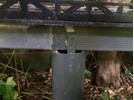
Basically, at each abutment there will need to be an arm at base level that extends to the same distance as the greatest point of the arc to prevent the overturning movement. The bridge will need to be fixed down to the abutments to stop it kicking up when the weight of the train is in the middle.
As this plan view.
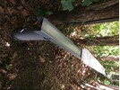


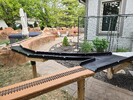
 They could probably supply preformed structural elements in CKD form, to your requirements, for shipping. Ally is not the heaviest of materials and CKD will reduce bulk for shipping. If you source the fixings locally you will save weight and possibly further shipping costs. Or just copy from pictures or even get one sent fully assembled. Max See their link here
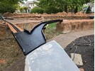


")

")