Brake van? - an idea

ol_hogger

Registered
23 Jul 2021
72
10
Germany
Country
Germany
Best answers
0
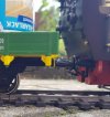
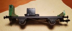
Being a beginner my track is a loop on the patio. Which I always considered as fairly level, however, it must be somewhat inclined so that rain may find the gutter. It is enough for a steam loco to react: Stalling an certains corners, running away downhill. Some sort of brake was needed, and this is what I came up with:

Brake_van_S.jpg

if you look closely, you will notice wooden brake shoes next to the purely ornamental rubber bows.
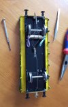
Brake_van_B.jpg

Look at this marvel of baling wire technology (actually made from paperclips). Brakes are held tight by a spring and released as soon as the waggon is dragged along. I found some lovely coloured rubber bands to increase friction. While not an engineering masterpiece it is good enough to check the concept.

Obviously, everything depends on the weight the waggon carries. I am trying to figure that out, as well as the best position in a train. Simply speaking, we are running "unfitted" trains coupled more or less loosely. I use chains (from paperclip wire, you may have guessed, your could use daisy chained clips right away.)

When this waggon is in front, right behind the engine, it will emulate the locomotive brakes as soon as slack in the train (from running downhill) begins to push it. Uphill, however, this behavior will not allow the momentum of the train help overcome eventual stalling spots, since as soon as the engine slows brakes will catch.

Let's put it on the tail, where every brake van should be placed. As opposed to the prototype, it will not keep the train stretched. Only when catching up with the slacking train braking will set in. Possibly, at that point the loco has already been pushed out at the bend.

Note that the engine itself is not effected. It works on the train alone.

I shall be satisfied when I have her run steady loops at a resposible speed without having to attend.
 
Last edited:
  • Like
Reactions: 1 user

3 minutes of fame

3d printing, electronics and trams
14 Dec 2020
573
154
Lincolnshire
www.mgnr.uk
Best answers
0
Country flag
Being a beginner my track is a loop on the patio. Which I always considered as fairly level, however, it must be somewhat inclined so that rain may find the gutter. It is enough for a steam loco to react: Stalling an certains corners, running away downhill. Some sort of brake was needed, and this is what I came up with:

View attachment 288412

if you look closely, you will notice wooden brake shoes next to the purely ornamental rubber bows.

View attachment 288413

Look at this marvel of baling wire technology (actually made from paperclips). Brakes are held tight by a spring and released as soon as the waggon is dragged along. I found some lovely coloured rubber bands to increase friction. While not an engineering masterpiece it is good enough to check the concept.

Obviously, everything depends on the weight the waggon carries. I am trying to figure that out, as well as the best position in a train. Simply speaking, we are running "unfitted" trains coupled more or less loosely. I use chains (from paperclip wire, you may have guessed, your could use daisy chained clips right away.)

When this waggon is in front, right behind the engine, it will emulate the locomotive brakes as soon as slack in the train (from running downhill) begins to push it. Uphill, however, this behavior will not allow the momentum of the train help overcome eventual stalling spots, since as soon as the engine slows brakes will catch.

Let's put it on the tail, where every brake van should be placed. As opposed to the prototype, it will not keep the train stretched. Only when catching up with the slacking train braking will set in. Possibly, at that point the loco has already been pushed out at the bend.

Note that the engine itself is not effected. It works on the train alone.

I shall be satisfied when I have her run steady loops at a resposible speed without having to attend.
This is my "active" solution. It uses a powered axle as the brake and is normally coupled directly behind the loco. With no power applied, the loco can drag it along, with wheels turning, but it has enough weight fitted that a little bit of reverse throttle will bring the train to a halt. On uphill sections, you can "cheat a little and give the loco a small boost!! It works very well and is very robust. Get the weight right and the throttle can be set to keep the train at a constant speed.

20210623_195524.jpg
 

dunnyrail

DOGS, Garden Railways, Steam Trains, Jive Dancing,
Staff member
GSC Moderator
25 Oct 2009
26,076
4,976
75
St.Neots Cambridgeshire UK
Best answers
0
Country flag
This is my "active" solution. It uses a powered axle as the brake and is normally coupled directly behind the loco. With no power applied, the loco can drag it along, with wheels turning, but it has enough weight fitted that a little bit of reverse throttle will bring the train to a halt. On uphill sections, you can "cheat a little and give the loco a small boost!! It works very well and is very robust. Get the weight right and the throttle can be set to keep the train at a constant speed.

View attachment 288426
Interesting how does this work, a clutch or some such?
Being a beginner my track is a loop on the patio. Which I always considered as fairly level, however, it must be somewhat inclined so that rain may find the gutter. It is enough for a steam loco to react: Stalling an certains corners, running away downhill. Some sort of brake was needed, and this is what I came up with:

View attachment 288412

if you look closely, you will notice wooden brake shoes next to the purely ornamental rubber bows.

View attachment 288413

Look at this marvel of baling wire technology (actually made from paperclips). Brakes are held tight by a spring and released as soon as the waggon is dragged along. I found some lovely coloured rubber bands to increase friction. While not an engineering masterpiece it is good enough to check the concept.

Obviously, everything depends on the weight the waggon carries. I am trying to figure that out, as well as the best position in a train. Simply speaking, we are running "unfitted" trains coupled more or less loosely. I use chains (from paperclip wire, you may have guessed, your could use daisy chained clips right away.)

When this waggon is in front, right behind the engine, it will emulate the locomotive brakes as soon as slack in the train (from running downhill) begins to push it. Uphill, however, this behavior will not allow the momentum of the train help overcome eventual stalling spots, since as soon as the engine slows brakes will catch.

Let's put it on the tail, where every brake van should be placed. As opposed to the prototype, it will not keep the train stretched. Only when catching up with the slacking train braking will set in. Possibly, at that point the loco has already been pushed out at the bend.

Note that the engine itself is not effected. It works on the train alone.

I shall be satisfied when I have her run steady loops at a resposible speed without having to attend.
Looking at this moving forwards the weak point could be the rubber bands that will perish over time in daylight. You may like to consider Black Heat Shrink that would likely reduce that problem and look less obtrusive on your next iteration of this interesting concept.
 

3 minutes of fame

3d printing, electronics and trams
14 Dec 2020
573
154
Lincolnshire
www.mgnr.uk
Best answers
0
Country flag
Interesting how does this work, a clutch or some such?

Looking at this moving forwards the weak point could be the rubber bands that will perish over time in daylight. You may like to consider Black Heat Shrink that would likely reduce that problem and look less obtrusive on your next iteration of this interesting concept.
Mine uses an Appletree motor-gearbox, which is sufficiently highly geared that the loco can turn it over. A bit like using engine braking in your car- or electrical retardation used in some full size locos, notably London Underground stock.
 

dunnyrail

DOGS, Garden Railways, Steam Trains, Jive Dancing,
Staff member
GSC Moderator
25 Oct 2009
26,076
4,976
75
St.Neots Cambridgeshire UK
Best answers
0
Country flag
Mine uses an Appletree motor-gearbox, which is sufficiently highly geared that the loco can turn it over. A bit like using engine braking in your car- or electrical retardation used in some full size locos, notably London Underground stock.
Oh yes I think you mentioned this in the past. I had at the time wondered if it would work mounted in a live steamer much like the SloMo but decided it would be too tricky.
 

ol_hogger

Registered
23 Jul 2021
72
10
Germany
Country
Germany
Best answers
0
Had to fiddle with the safty valve and water gauge of Else, little time for systematic tests.

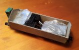
The brake wagon will hold the train in the incline. In order to prevent derailing I weight it down with two small tins of paint (half emtpy) which would scale out at some 200 g or half a pound.

Coupl_top_X.jpg

Note the stretched state, brakes released.

Coupl_side_X.jpg

Coupl_low_X.jpg

As the train catches up with the locomotive the chain will go slack.

Coupl_low_C.jpg

Note the Z-bend in the actuating wire now readily visible.

Coupl_side_C.jpg

In order to observe this action with a moving train I increased the load to maybe 700 g or 1.5 pounds. Before, the action was too fleeting to discern, if anything was happening at all.

To be honest, these pictures were staged. I could not manage to shoot while it was moving since there were surprisingly short stretches of actual braking. And even more surprising: The rubber bands stood up well for a trial. Heat shrink tubing will be certainly considered when I start to do this over for "real".

(And yes, as an alternative I have two LEGO inertitia motors sitting here awaiting the next experimental wagon.)
 

ol_hogger

Registered
23 Jul 2021
72
10
Germany
Country
Germany
Best answers
0
Stubbornly, I wanted to avoid R/C and did not pay much interest to the electric solutions in the contributions above.

But London Underground rang a bell: Electro-dynamic braking. Usually, there is an array of resistors shunted in as appropriate conversing to heat the energy created by the traction motors working as generators. (Modern semi-conductors even allow feeding the resulting current back to the grid.)

Every DC-motor will work as a generator. Let's clip a lightbulb to its terminals. With the shaft turning slowly, the bulb will be no more that an odd shaped piece of wire shorting the circle. But as speed increases, the bulb will start to glow brighter and brighter while its electrical resistance rises. (Those old timers from before the electronic age will remember this from their bicycles.) More light means more work, more drag.

Connected to a wagon axle we will get little resistance when starting, yet ever increasing braking action as the train is picking up speed. Self regulating speed control more sensitive than my old mechanical proposal!

All depends on the motor and lightbulb you use. Check that box of spare bulbs for your old car. (Your new one has got LEDs, hasn't it?). Maybe the brake light? Then there are low voltage lighting systems with neat sockets and in a variety of wattages available.
 

3 minutes of fame

3d printing, electronics and trams
14 Dec 2020
573
154
Lincolnshire
www.mgnr.uk
Best answers
0
Country flag
Stubbornly, I wanted to avoid R/C and did not pay much interest to the electric solutions in the contributions above.

But London Underground rang a bell: Electro-dynamic braking. Usually, there is an array of resistors shunted in as appropriate conversing to heat the energy created by the traction motors working as generators. (Modern semi-conductors even allow feeding the resulting current back to the grid.)

Every DC-motor will work as a generator. Let's clip a lightbulb to its terminals. With the shaft turning slowly, the bulb will be no more that an odd shaped piece of wire shorting the circle. But as speed increases, the bulb will start to glow brighter and brighter while its electrical resistance rises. (Those old timers from before the electronic age will remember this from their bicycles.) More light means more work, more drag.

Connected to a wagon axle we will get little resistance when starting, yet ever increasing braking action as the train is picking up speed. Self regulating speed control more sensitive than my old mechanical proposal!

All depends on the motor and lightbulb you use. Check that box of spare bulbs for your old car. (Your new one has got LEDs, hasn't it?). Maybe the brake light? Then there are low voltage lighting systems with neat sockets and in a variety of wattages available.
Nice idea, but a small flaw in the plan is that the resistance in the filament rises, which reduces the braking effect. You would need to see a fall in resistance to increase the braking effort. Low resistance = more current flow, so more braking.

A solution might be some sort of speed sensing circuit - probably an optical encoder on the back of a wheel, linked to a bank of relay switched resistors. As the speed increases, more resistors are switched into the circuit, reducing the resistance and increasing the braking effort.

You will need to pick a motor with fairly heavy duty brushes - or something like a dynamo, which is just a spinning magnet and fixed coils. Working out the gearing so that the motor can apply enough braking while still being able to be turned over by the loco off load will be an interesting challenge!!

My R/C solution could be adapted by simply removing the r/c and using a stand alone servo driver board to set the speed controller to a fixed value. This will try and rotate the wheels at a fixed rate and the gearbox I've used gears the motor down enough that it won't over speed on most inclines. All you would then do is to set the regulator to the desired setting and then the same with the speed controller. Once running, the speed should be relatively constant, irrespective of gradients or anything other than severe curves.

I find with my brake van, I control the speed quite a lot. On curves, it needs a little bit of effort to overcome the friction, while on the long downhills - about 8M and a gradient change of 3" over the distance, it needs backing off and some braking before the bend at the end!
 

ol_hogger

Registered
23 Jul 2021
72
10
Germany
Country
Germany
Best answers
0
Another proof of concept:

We had a mysterious Lego brick here.

These are sold by several specialist stores for used LEGO, if they are specialized, they know what they are selling. Anyway I received two friction motors and put them into my project for the sake of symmetry.

MmCarT.jpg

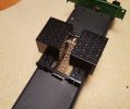
The motor unit is held in place by two tabs front and rear. I am in the lucky position of having a well stocked Wilesco dealer in reach. While Wilesco never claimed to do anything but toys, all their parts can be purchased as spares and come in useful (and he's got a drawerful, from which I could pick). Chain and sprockets are from their fire truck and steam lorry line.

MmCarL.jpg

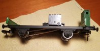
Sprockets are for 4 mm axles, perfect for Maxi. I had to open up the second one to 5 mm so it would slip onto a LEGO cross-shaped shaft.

MmCarU.jpg
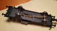
Accept my apologies for the crudely hacked out aperture. As you know, I am better at bending paper clips.

MmCarR.jpg

If you look closely you may notice that this side of the LEGO motor can be popped out. You are faced then with four screws which fix the mechanism. I was not sure whether it would come out in one or in its indiviudal pieces, so I left it at that for now.

I have already had a test run, but it gets dark too early for pictures. Quite some weight is needed for adhesion, a pound of orange marmelade this time. The effect on Else (still without R/C) is as intended: Speed variation is less between level and slightly inclined stretches, which results in responsible curve speeds throughout.
 
Last edited:

dunnyrail

DOGS, Garden Railways, Steam Trains, Jive Dancing,
Staff member
GSC Moderator
25 Oct 2009
26,076
4,976
75
St.Neots Cambridgeshire UK
Best answers
0
Country flag
Nice idea, Incan see that working in a Tender as well though there may be some limitation of getting weight into the tender. Linking the 2 sets of wheels may also be an advantage. Delrin chain would work for that or some more of that Wilesco stuff.
 

ol_hogger

Registered
23 Jul 2021
72
10
Germany
Country
Germany
Best answers
0
Sunshine today, momentum car in action.

MmCartrainL.jpg

MmCartrainF.jpg

Finally, I can sit back (for a couple of laps, until the next water stop), or take pictures.
Those tins look interesting enough, but I shall have to find some permanent weight to be hidden under some tarpaulin.
 
Last edited:

Fred2179G

Registered
20 Apr 2017
1,054
186
USA
Best answers
0
Country flag
Every DC-motor will work as a generator.
As an ex-slot car guy, I assure you that a direct short works much better than a bulb. From
Why Do I Need a Controller

Brakes are achieved by connecting the motor terminals together. This makes the motor act like a dynamo and slows itself down quickly. The less resistance on brake the sooner the car will stop - so low resistance contacts and thick wire help. This is called "Dynamic braking".

Basically, the back-emf produced by the spinning motor has to work within the magnetic field of the motor and opposes the motion of the motor shaft. The faster it is spinning, the more the braking effect.

I suppose you could use a mercury switch to detect that the train is going downhill and to then switch on the dynamic brakes!
 
8 Mar 2014
7,806
972
San Diego
Country
Armenia
www.elmassian.com
Best answers
0
Country flag
More simply, the motor acts as a generator, shorting the output puts a greater electrical load on the generator, thus increasing the mechanical resistance since more "work" is required to generate more power (laws of physics)

BEMF is there, but not the major factor (if BEMF was greater than the forward motion, no motor could function)
 

ol_hogger

Registered
23 Jul 2021
72
10
Germany
Country
Germany
Best answers
0
Thank you all, Electro Experts.

I can see two approaches now. (Given that I try to get along without R/C and batteries):

1. The booster/brake wagon is no less than a small remote controlled battery powered extra locomotive. Put in forward, it will help push the train, carefully put on counter current it will slow the train. Could this counter current be created by a generator on the car? Something like a perpetuum mobile hooked up wrong way round: not G=M, but GxM where G is the generator, M the motor and = vs. x the wiring?

2. The slot car brake could be controlled by an intermittent switch driven from the axle. The faster we go, the more brake impulses. I have got a Märklin Maxi "sound" tender where a finger or cam triggers the chuffs created by a noise generator.

What do you think?
 

3 minutes of fame

3d printing, electronics and trams
14 Dec 2020
573
154
Lincolnshire
www.mgnr.uk
Best answers
0
Country flag
I don't think you could ever generate enough power from an on-board generator, but certainly a phase locked loop motor controller would permit a motor to be run at a constant speed. A suitable design would apply braking effort during over speed and would operate much as a governer. Not sure about returning power to the batteries however...
 
8 Mar 2014
7,806
972
San Diego
Country
Armenia
www.elmassian.com
Best answers
0
Country flag
Simple is good..

Yes, turn a motor as a generator, take the output and put to a motor, wired "backwards"... but why do that when you can just have a motor being turned by the wheels, and an adjustable load on it, like a pot, to adjust the load? Same as dynamic brakes.

Greg
 

ol_hogger

Registered
23 Jul 2021
72
10
Germany
Country
Germany
Best answers
0
Plucked some lead sheeting from the roof for weight.

Gable_top.jpg

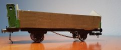
Time to think about the "decoration". Gable ends: A tarpaulin cover would provide some leeway to accommodate technical changes that may or may not occur. A nice variation to the somewhat boring Märklin Maxi stock.

Gable_front.jpg

Time to sew up the cover and finish details.

Gable_side.jpg