G-force1
Prevarication Rules!
The proper operation of the T.V.B.L. hinges on the changing of one set of points at the entry and exit of the balloon loop, so that 'Up' trains traverse anti-clockwise and 'Down' trains clockwise. Normally this would be simply a case of a trailed point, however here there is also a passing loop to consider, which was added later. The balloon loop joins at the start of the p/loop. 'Up' trains will also pass to the left side of the p/loop and down trains the right.
 (450 x 600).jpg")
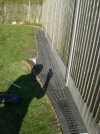
The original method was by a simple rod-linkage (just visible above) with bell-cranks. Unfortunately this linkage has suffered the ravages of the weather and the so-called stainless pivot links (aircraft type) proved to be only plated. The pivots then rusted and became very tight in the cranks making the whole thing unreliable.
The thought was that it should be possible to motorise the b/loop point and leave the p/loop entry point sprung left. Getting power to the motor was possible with a very long lead so battery power was considered and thought possible with solar charging. Not wanting to have to manually operate the point automation was required and therefore a micro-switch needed to be added to the p/loop entry point so that a 'Down' train would trip it as it exited the p/loop. The motorised point will trail from the b/loop, but if that proves unreliable a second micro-switch could be added to the p/loop exit point which is currently sprung right.
 (600 x 450).jpg")
The switch is mounted at an angle to increase its operating movement, it is also set 'hair-trigger' to give the longest 'closed' time though it seems more than adequate ATM. It has a clamp on the near end rather than another screw, so that future adjustment is possible. A minor problem is that my lightest waggon (W&L flat) isn't quite heavy enough to trigger it on its own, I may just add a touch of lead underneath, rather than mess with the spring weights, as it's very slight. The switch does add a little extra to the earlier spring.
 (600 x 450).jpg")
The original method was by a simple rod-linkage (just visible above) with bell-cranks. Unfortunately this linkage has suffered the ravages of the weather and the so-called stainless pivot links (aircraft type) proved to be only plated. The pivots then rusted and became very tight in the cranks making the whole thing unreliable.
The thought was that it should be possible to motorise the b/loop point and leave the p/loop entry point sprung left. Getting power to the motor was possible with a very long lead so battery power was considered and thought possible with solar charging. Not wanting to have to manually operate the point automation was required and therefore a micro-switch needed to be added to the p/loop entry point so that a 'Down' train would trip it as it exited the p/loop. The motorised point will trail from the b/loop, but if that proves unreliable a second micro-switch could be added to the p/loop exit point which is currently sprung right.
The switch is mounted at an angle to increase its operating movement, it is also set 'hair-trigger' to give the longest 'closed' time though it seems more than adequate ATM. It has a clamp on the near end rather than another screw, so that future adjustment is possible. A minor problem is that my lightest waggon (W&L flat) isn't quite heavy enough to trigger it on its own, I may just add a touch of lead underneath, rather than mess with the spring weights, as it's very slight. The switch does add a little extra to the earlier spring.


")


 (600 x 450).jpg")
 (600 x 399).jpg")
 (600 x 450).jpg")
 (600 x 450).jpg")
 (600 x 450).jpg")