Aristocraft Center Cab help

Jeff N

Registered
Country flag
Hi,
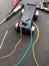
I have a center cab that I wanted to convert to DCC using a massoth XLS decoder. When I dug into it I found that the motor and track wires seemed to be isolated. I used a jumper wire to connect the two blocks and was, I thought, careful to make sure that the motor and track leads were connected properly. When I did a continuity check of the now connected blocks the motor wires show continuity but the track contacts did not. I thought perhaps to complete the circuit it should be on the track. When I put it on the track the central station says there is a short on the track. So, does anyone know if the track wires and motor wires are actually isolated on this engine or am I completely overlooking something else? I found the girr.org site that had a lot of helpful information about this little engine but, I've still managed to muck it up somehow. This is my first attempt at anything this ambitious as up till now most of my mods were plug and play type projects. Thank you!
 
Take the jumper(s) off
Now you need 4 wires/points of connection.

  1. track right
  2. track left
  3. motor plus
  4. motor minus
use the ohmmeter to test 1 and 2, they should have NO connection to ANY other wire. In addition check the #1 to be sure it connects to the right wheels only. Do the same for the left wheels on #2

Now check #3 and #4, they should have no connectivity to any of the other wires except between themselves, and between 3 and 4 you should have something more than zero ohms, like 7 to 50 ohms.

now you are ready to wire these 4 leads to your decoder... test... (do not start hooking up lights or anything else)

if you put a jumper between the track leads and the motor leads (one track to one motor, the other track to the other motor) of course the programming track would indicate a short... and if you put on the mainline it would buzz..

Greg
 
Where have you picked up track and motor wires?

You will probably find the two motor-blocks are 'mirror-images (one is 180 degrees to the other, but they are wired identically.. This means track +ve. on one block is track -ve. on the other.

It is 'easier to lift the four wires from the mainboard in the loco, and not route through it for the motors. You then use decoder +ve. and -ve. through a relay to feed the mainboard for the lights. This DPDT rely is 'off' for forwards, and 'on' for backwards, changing the polarity of the power to the mainboard.

PhilP.
 
Thank you gentlemen. I will try these suggestions and see what I get. Greg, this loco does not have a socket like the one outlined on your website. It had two plugs for each motor block. one for track power one for motor. Each with two wires. Those plugged into a small board that the lighting came off of.
 
I checked the wires as outlined. 1 (white/red) and 2(brown/black) did not register anything on the meter when checked against all other wires. I did get continuity between the white/red wire and the left side wheel and the brown/black wire and right side wheel. The green/green and yellow/blue wires register around 8-9 on the meter when checked. When I checked 1(white/red) and 2(brown/black) on the other motor block the meter did not register when checked with the other wires. When I checked 1 and 2 to the wheels the brown/black wire is the left side and the white/red is the right side wheel. As Phil mentioned they are opposite. So these appear to be Okay?
When I connect both motor blocks to the decoder how do I tell which is + and - or does it matter? Also, to keep the polarity(right word?) the same do I need to connect 1 to 2 and 2 to 1? Not sure if I am asking that correctly. Thanks very much!
CC-2.jpg
 
Designate one end of the loco as the front.

Remember which way the motor blocks sit under the loco (I always mark with arrows pointing forward), and ensure that both the left side track pickup wires go to one decoder input, and both the right side track pickup wires got to the other decoder input.
Connect up the motor wires to the decoder motor outputs. Power up the loco slowly on DC, and check which way the wheels turn - if you've got them running opposite then swap one set of motor wires.

That should get you going.

Ideally it's useful if under DC the loco runs the same way down the track as a non-DCC loco, and under DCC when commanded to run forwards it runs in the direction you would expect. If it runs opposite to a DC loco then try swapping the track pickups. If it runs the wrong way on DCC then swap both the motor wires.

Once happy with all that, then it's time to connect any directional lighting :)
 
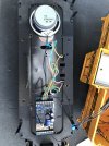
Thank you all your help. This is what I ended up with. It’s running fine. I’m going to address the wiring mess on another day. EA6F59D4-955F-4757-A96C-5803B76004B0.jpeg
 
Back
Top Bottom