Alternating Station Circuit

Lgb train

Registered
13 Nov 2022
11
0
24
Hhsjsjsjs
Best answers
0
Country flag
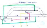
There are 2 reed switches, being one in each 17100. If only 1 loco had a magnet on the base the system would certainly not work.
When the first train when over the reed it switched the track and stopped then I put that same train on other track and nothing changed.
 
8 Mar 2014
7,806
972
San Diego
Country
Armenia
www.elmassian.com
Best answers
0
Country flag
So, looking at the "manual" it appears the 17100 has 2 diodes in it, and basically given an "input" of AC, you can have the switch pass either negative pulses or positive pulses.

I gather the little circles are the external connections. No idea why the internal biasing magnet is shown as a box with a slash.

LGB_17100.jpg

Typically fed from AC

so in your circuit:
442635_2938C4C3-E7EE-4FF4-AD3F-CF607AD0D425.jpeg

You want one OR the other 17100 triggered.

What do you think happens if BOTH are triggered at the same time?

You apply FULL AC to the switch motor, which will not move it (it might buzz).

You need a way to be sure once triggered, then the loco get's OFF the reed switch.

You need a circuit that only allows the reed switches to act once and then that one is disconnected until the switch is tripped again
 

phils2um

Phil S
11 Sep 2015
1,522
423
Ann Arbor, Michigan
Country
United-States
Best answers
0
Country flag
I'm going to ask a stupid question. You are using an 18V AC power source (connections 3 & 4) for the EPL drives correct? If you are using DC power to connections 3 & 4 as shown in your drawing then only one the reed switches will work because of the internal diodes. And, your symptoms will be exactly duplicated.

By the way, there is no internal biasing magnet in either the 1700 or 17100 EPL magnetic reed contact switches-
No idea why the internal biasing magnet is shown as a box with a slash.
Not sure what you are looking at here Greg.
 
Last edited:
8 Mar 2014
7,806
972
San Diego
Country
Armenia
www.elmassian.com
Best answers
0
Country flag
1. stated in post #3 that connections "3 & 4" go to AC. (this answers Phil's question in post 23)

2. Post #12 states that the continuous application of power (determined that he moved the switch manually and it immediately switched back) means a reed switch is stuck or is being continuously triggered. Some testing is suggested.

3. Post #14 the OP states he pulled it all apart, re-connected and it now behaves differently

4. Post #22 indicates that I believe that the system is continuously triggering, same as Post #12

5. In response to Phil's question at end of post #23: Sorry, it was in a different illustration:

83685_adcc81c0f726d6c548023e343ea076f1.png


I used a different illustration, the one above does not make it clear where the terminals are, it also implies the 2 diodes are connected to each other, and it has a square box with a slash through it I guess to represent that the switch is magnetically operated, I did not like this illustration... I accidentally left the comment after getting rid of the illustration..

Greg
 

phils2um

Phil S
11 Sep 2015
1,522
423
Ann Arbor, Michigan
Country
United-States
Best answers
0
Country flag
OK, in hope of helping solve LGB Trains dilemma let me re-iterate a few things.

Post#1 by Mike asked some questions about using LGB EPL magnetic contacts and an LGB EPL turnout drive with supplementary switch to control trains entering a two track station as depicted in his original post.

This post was answered by Jon in Post#2 and DavidC in Post#3. I'm assuming the answers were to Mike's satisfaction as he lets the thread lapse.

There is nothing wrong with the circuit as originally posted by Mike and it will function as expected provided the individual components are functional and the circuit is powered by AC voltage. The whole premise of LGB's EPL analog control logic was to rely on half-wave rectification of AC current to give the option of either positive or negative control pulses. The control pulse polarity option significantly reduces the wiring and component complexity otherwise needed to accomplish the same analog control result using straight DC power.

Eight months on LGB Trains revives Mike's thread in Post#4 being unable to duplicate the circuit functionality (this in spite of quoting Post#3 by DavidC spelling out the need for AC power). The issue he was having in post#4 (and again in Post#21) is exactly duplicated by powering the circuit with DC. Hence, my "stupid question" in Post#23.

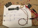
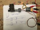
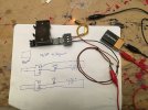
Without having a meter with a diode test function it is difficult to check if LGB 1700 or 17100 track contacts are working properly. Attached is a simple circuit and pictures you can use to test the contacts without needing a meter. This does need DC in the way of a battery. The first pic is wired as number "1" and no magnet in close enough proximity. The light is off. Red alligator is battery positive and Black is battery negative. Pic 2 show the same setup with the magnet on the contact and the light is on. Pic 3. is wired as "2" to test the other diode.

1700 test - 1 (1).jpeg 1700 test - 1 (2).jpeg 1700 test - 1 (3).jpeg

Edit added: I did not take a pic with the polarity of battery reversed from the "on" condition. However, because diodes only let current flow in one direction, the light will stay off even when the magnet closes the reed switch. This is why the second contact will not throw the switch when the station circuit in Post#1 is powered by DC.
 
Last edited:

korm kormsen

Registered
24 Oct 2009
2,765
296
Country
Paraguay
Best answers
0
Country flag
...

83685_adcc81c0f726d6c548023e343ea076f1.png


I used a different illustration, the one above does not make it clear where the terminals are, it also implies the 2 diodes are connected to each other, and it has a square box with a slash through it I guess to represent that the switch is magnetically operated, I did not like this illustration... I accidentally left the comment after getting rid of the illustration..

Greg
Greg,

in the epl system this makes perfect sense.
using the 1700 or 17100 only one of the outlets of each reed is connected to a common wire (for two reeds) to the switchmotor.
the rectangular with the slash must represent the third element besides reedcontact and diodes in those 17(1)00s. a lent-formed "thingy" (i always forget it's name), in paralel to the reed, that somehow hinders the reed to burn shut too quickly.

in the pic below one can see it (not very clearly)


reeds.JPG
 
8 Mar 2014
7,806
972
San Diego
Country
Armenia
www.elmassian.com
Best answers
0
Country flag
Korm, the only issue I had was with the drawing, the "box" with the slash through it...

not a good symbol for the biasing magnet inside...

I know what it is, it helps keep it open when not activated, and you have to overcome the mechanical bias of the spring with a stronger magnetic field.

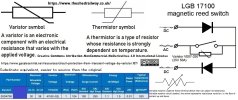
I just commented on using a strange drawing, and the implication is that it is a electronic component... although perhaps it is not meant to be the physical magnet but perhaps a thermistor...

AHH! I looked it up, the US symbol is something that makes sense:

thermistorsymbol.png

So indeed it is an inrush resistor to help from burning the contacts..... learn something every day! Nothing to do with the movement, all about current management... Low resistance to help offload the contacts, and then the current changes the resistance back to high impedence most likely.

I'd say it's confusing to most people, and I don't think this feature is described in the "manual"... it would be more helpful to put the default state of the reed on the diagram, like "N.O." (normally open). Ahh, since I am 1/4 German, I understand the thinking: silly American / dummkopf!


83685_adcc81c0f726d6c548023e343ea076f1.png
 

Lgb train

Registered
13 Nov 2022
11
0
24
Hhsjsjsjs
Best answers
0
Country flag
So, looking at the "manual" it appears the 17100 has 2 diodes in it, and basically given an "input" of AC, you can have the switch pass either negative pulses or positive pulses.

I gather the little circles are the external connections. No idea why the internal biasing magnet is shown as a box with a slash.

LGB_17100.jpg

Typically fed from AC

so in your circuit:
View attachment 308224

You want one OR the other 17100 triggered.

What do you think happens if BOTH are triggered at the same time?

You apply FULL AC to the switch motor, which will not move it (it might buzz).

You need a way to be sure once triggered, then the loco get's OFF the reed switch.

You need a circuit that only allows the reed switches to act once and then that one is disconnected until the switch is tripped again
So turns out I was using DC instead of AC and I tried it with AC and it worked.
 

korm kormsen

Registered
24 Oct 2009
2,765
296
Country
Paraguay
Best answers
0
Country flag
just to confuse us all...

i looked it up with a spyglass.
inside the 1700 (i have got only this older version) the "thingy" is marked: H J0 39Z1
google now found me: https://www.datasheetarchive.com/VARISTOR 39Z1-datasheet.html

when i showed that to the chinese guy in the electrics-store and asked to sell me some of these "cosas" (cosa = thing) he sold me these: 7K820 7 6
google now told me: https://www.maritex.com.pl/product/attachment/55596/VXXNXXX.pdf

wiki tells me: A varistor is an electrical resistance that varies with the applied voltage.[2] Also known as a voltage-dependent resistor (VDR), it has a nonlinear, non-ohmic current–voltage characteristic that is similar to that of a diode.

on that page wiki tells me that the rectangle with the slash is: Modern varistor schematic symbol, which is the same as a thermistor symbol[1]

further it tells me: A thermistor is a type of resistor whose resistance is strongly dependent on temperature, more so than in standard resistors.... Negative Temperature Coefficient (NTC) thermistors have less resistance at higher temperatures, while Positive Temperature Coefficient (PTC) thermistors have more resistance at higher temperatures.

well, my tecnical knowledge of electric things consists of : try and fry, then repeat, till i reach try and fly.

so my personal resumen is, that it only matters, that the "thingy" has a form like a lent and two legs.

but my homespun 1700-ish reeds functioned during the last 15 years or longer (not sure, when i made the first batch)
 
8 Mar 2014
7,806
972
San Diego
Country
Armenia
www.elmassian.com
Best answers
0
Country flag
My only confusion is why you are posting this.

The only helpful part would be to determine it is a NTC, and that it helps reduce the arcing during the make and break cycles. Probably the make, but if you have an inductive load, it would help at the other end.

Anyway, suffice it to say that LGB added a component to try to reduce wear on reed switch contacts.

Greg
 

phils2um

Phil S
11 Sep 2015
1,522
423
Ann Arbor, Michigan
Country
United-States
Best answers
0
Country flag
Anyway, suffice it to say that LGB added a component to try to reduce wear on reed switch contacts.
I'm still often amazed at the lengths the original Lehmann Bros. went to making their products "bullet proof".
 

dunnyrail

DOGS, Garden Railways, Steam Trains, Jive Dancing,
Staff member
GSC Moderator
25 Oct 2009
26,164
4,989
75
St.Neots Cambridgeshire UK
Best answers
0
Country flag
I'm still often amazed at the lengths the original Lehmann Bros. went to making their products "bullet proof".
Indeed so, we will never see their like again.
 
8 Mar 2014
7,806
972
San Diego
Country
Armenia
www.elmassian.com
Best answers
0
Country flag
Yeah, and with the advent of low current logic controls, finding reed switches that handle high current without burning or fusing closed will be more and more difficult.

Train-Li put high current reeds in their turnouts to change the points polarity (and frog I believe), It had a huge rectangular contact, but I believe that has changed due to availability too.

Merely substituting an "off the shelf" reed will probably not have the lifespan.

Greg
 

dunnyrail

DOGS, Garden Railways, Steam Trains, Jive Dancing,
Staff member
GSC Moderator
25 Oct 2009
26,164
4,989
75
St.Neots Cambridgeshire UK
Best answers
0
Country flag
My TrainLine 45 curved point was the only one with a Reed Switch burnt out on an unexpected derailment and short. Was replaced with a micro switch which worked just fine till I went Dead Rail.
 

fairflixt

Vincent
27 Sep 2021
56
3
124
US
Best answers
0
Country flag
Seeing this discussion reminded me of a similar discussion with questions from me on the EPL system a year ago. Here is a link to what I found identifying the third component as a varistor and linking to a drawing of the 1710(0) with clearer descriptors. Confusingly, wikipedia states that the varistor and thermistor use the same symbol. Hope that helps!
 

JimmyB

Now retired - trains and fishing
23 Feb 2018
6,946
921
69
Weston-super-Mare
www.tumble-down-falls.co.uk
Best answers
0
Country flag
both devices vary resistance with heat... more importantly is PTC or NTC
Not according to what I have read:

What is the difference between a varistor and a thermistor? One is voltage sensitive the other temperature sensitive. A varistor is resistor that changes resistance with applied voltage. A thermistor is one that changes value with temperature.