3D printable traction motor case

Melbournesparks

Registered
30 Sep 2015
323
424
City of Eltham
Best answers
0
Country flag
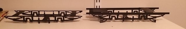
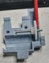
Anyone who builds their own rollingstock has probably run into the problem of how to power it, the lack of cheap and easily available motor blocks has been a huge barrier to entry. To try and solve this problem I've been working on a 3D printable traction motor case that uses cheap and easily obtainable parts, designed so that it can be easily adapted to power just about any 45mm gauge rollingstock. The STL file is now up on Thingiverse for anyone who wants to make their own. The prototype versions have been powering the W class and toast rack tram for quite a number of real kilometers now with good results, on a long and steeply graded line.
45mm gauge traction motor case by Melbournesparks|

Here's ebay links for the motor and gears used. Ebay links are unlikely to stay current forever but you should be able to find equivalent parts by searching:

motor FF-130SH 1pcs FF-130SH DC 12V 4500RPM High Torque Great Torsion Mute Micro Motor for DIY | eBay
gear 1 9T 50PCS X 9T Plastic Spur Gear Teeth=9 Aperture:2mm 0.5 Modulus Accessories 1.95MM | eBay
gear 2 34T+12T 100pcs 34 Teeth Electric Machanical Model Motor Gear Wheel 3412-2B 605322478027 | eBay
gear 3 40t 100PCS 40 Teeth 3mm Hole Diameter Plastic Gear Wheel for RC Car 605322558002 | eBay

tractionmotor2 (Medium).jpg
 
  • Like
  • Love
Reactions: 4 users

DafyddElvy

1:22.5 & 15mm Scale Trams, , NG Steam Railways
10 Feb 2021
984
96
West Lothian
Country
Scotland
Best answers
0
Country flag
Thank you very much, if the british postal service didn't hold on to things for so long trying to work out how to hit me for tax I probably would have had the motors sooner.

Just waiting on the double gear to arrive via the postal system here.

The motor fits the housing like a glove.

This is going to save me an absolute fortune in traction motors, thanks for sharing.
 

Melbournesparks

Registered
30 Sep 2015
323
424
City of Eltham
Best answers
0
Country flag
Thank you very much, if the british postal service didn't hold on to things for so long trying to work out how to hit me for tax I probably would have had the motors sooner.

Just waiting on the double gear to arrive via the postal system here.

The motor fits the housing like a glove.

This is going to save me an absolute fortune in traction motors, thanks for sharing.

Best of luck, hopefully they provide reliable service. I haven't had any problems with the units I have running here yet.
21E.jpg

This reminds me I'm still in the process of developing a fully printable 21E truck using these traction motors suitable for the bachmann trams.

21e_toastrack.jpg
The prototype has been fitted to the toast rack tram. It uses the same screw holes and provides a bit of flex for rough track, though I was going to refine the very messy prototype installation a little to make it a fully "drop in" conversion before posting the files.
 

DafyddElvy

1:22.5 & 15mm Scale Trams, , NG Steam Railways
10 Feb 2021
984
96
West Lothian
Country
Scotland
Best answers
0
Country flag
KW Trams produces a 6ft (84mm) wheel base 21E truck for £8 with separate axle boxes which I have sprung on my first two Bachmann tram conversions.
Unfortunately he does only produce the one wheel base.

A 3D printed truck side would allow my 3D CAD friend to produce different wheel base truck sides, I did mention the idea to him a few weeks ago when visiting Crich and Beamish.

I have only converted one toast rack at the moment and that has been to a trailer.

Now you have helped with an economical traction motor conversions can start in earnest with the rest of the Bachman Tram fleet, and I have no excuse not to build the bogies for MER No. 23.
 
  • Like
Reactions: 1 user

Melbournesparks

Registered
30 Sep 2015
323
424
City of Eltham
Best answers
0
Country flag
KW Trams produces a 6ft (84mm) wheel base 21E truck for £8 with separate axle boxes which I have sprung on my first two Bachmann tram conversions.
Unfortunately he does only produce the one wheel base.

A 3D printed truck side would allow my 3D CAD friend to produce different wheel base truck sides, I did mention the idea to him a few weeks ago when visiting Crich and Beamish.

I have only converted one toast rack at the moment and that has been to a trailer.

Now you have helped with an economical traction motor conversions can start in earnest with the rest of the Bachman Tram fleet, and I have no excuse not to build the bogies for MER No. 23.

Oh yeah nice, I have not heard of them though it looks like they have some good products, especially with the sprung axle boxes. I suspect the shipping cost would be uneconomical for me in the southern hemisphere though!
This one was 95mm wheelbase as designed, though it could be easily be modified to suit other wheelbases if there's any requests.
 

DafyddElvy

1:22.5 & 15mm Scale Trams, , NG Steam Railways
10 Feb 2021
984
96
West Lothian
Country
Scotland
Best answers
0
Country flag
The two styles of trucks I have, the lower one for toast racks.

For the enclosed trams I have put a section of H brass between the underside of the body and top of the truck, soldered to the H brass are some short pieces of brass angle for cables to be tidied away, the centrally mounted cross piece carries the charging socket.

I am wondering if your truck sides printed with removable axle boxes (for me anyhow) and inclusive of the cross plates I have soldered to the casting and H brass, would have the required strength if a piece of flat brass was glued to the cross pieces, if that makes sense, then the whole truck could be printed as a single piece.

My method of fixing the truck assembly to the enclosed tram body is a single M1.5 x 3mm screw at each end through the truck end cross plates in to the body shell floor, to fix the toast rack truck in place I have used the models weight fixing stands with the screw heads catching the central cross member.

Would you mind sharing your side frame CAD file for my friend to play around with a couple of ideas?
 

Attachments

  • 20210621_010406.jpg
    20210621_010406.jpg
    88.8 KB · Views: 0

FatherMcD

Registered
13 Mar 2014
386
35
Idaho
Country
United-States
Best answers
0
Country flag
I have a rough running Bachmann toastrack that will probably need a new motor(s). Would you mind clarifying how the motor case itself is mounted to the Bachmann chassis? Thanks,
 

DafyddElvy

1:22.5 & 15mm Scale Trams, , NG Steam Railways
10 Feb 2021
984
96
West Lothian
Country
Scotland
Best answers
0
Country flag
I have a rough running Bachmann toastrack that will probably need a new motor(s). Would you mind clarifying how the motor case itself is mounted to the Bachmann chassis? Thanks,
What I have done is build a new truck, which is not as scary as it might sound.

Are you using track or battery power is my first question, this will help me know how to answer you better?
 

FatherMcD

Registered
13 Mar 2014
386
35
Idaho
Country
United-States
Best answers
0
Country flag
What I have done is build a new truck, which is not as scary as it might sound.

Are you using track or battery power is my first question, this will help me know how to answer you better?
Battery power.
 

FatherMcD

Registered
13 Mar 2014
386
35
Idaho
Country
United-States
Best answers
0
Country flag
And I do have a 3D printer.
 

Melbournesparks

Registered
30 Sep 2015
323
424
City of Eltham
Best answers
0
Country flag
I am wondering if your truck sides printed with removable axle boxes (for me anyhow) and inclusive of the cross plates I have soldered to the casting and H brass, would have the required strength if a piece of flat brass was glued to the cross pieces, if that makes sense, then the whole truck could be printed as a single piece.


Would you mind sharing your side frame CAD file for my friend to play around with a couple of ideas?

To give a bit of an idea what I was going for this is the complete unit:

21E_assembled.jpg
It sounds like it is broadly similar to what you describe. The key difference is that instead of having the axle boxes move individually the side frames are a single piece and twist relative to each other. The left cross member has a single screw on which it tilts laterally, the right one is rigidly fixed to the car body. The side frames are held to the cross members by an M2 screw at each end. The central cross member is not fixed to the side frames, it just supports the back of the traction motor cases.

The holes in the cross members are all designed to line up with the existing screw holes in the bachmann tram car body, though some shortening of the plastic mounting posts will be needed to get the floor height right.

The reason why I went for a rigid side frame rather than separate moving axle boxes is it allows the use of a small flanged roller bearing in the axle boxes, as well as making the whole thing a lot stiffer for printing in PLA. For my printer at least I think the side frames need to be separate parts so they can print inside face down on the table. I could potentially make a version with the sideframes rigidly fixed to the cross members and separate axle boxes, though I'm not sure what orientation you would print it in to make sure everything was fully supported. I would think it would probably need to be ABS too, just because without the axle boxes in place (and presumably the primary suspension springs?) the frame on its own is pretty thin.

I have a rough running Bachmann toastrack that will probably need a new motor(s). Would you mind clarifying how the motor case itself is mounted to the Bachmann chassis? Thanks,

Hopefully this answers that as well.

I was going to wait until I've had a chance to print and test fit a prototype to make sure everything lines up properly before uploading to thingiverse but the sideframe on its own is attached if you want to see if you can make it fit your purposes.
 

Attachments

  • 21E_sideframe.zip
    1.3 MB · Views: 0

FatherMcD

Registered
13 Mar 2014
386
35
Idaho
Country
United-States
Best answers
0
Country flag
I see, you are really replacing the entire Bachmann chassis and the motor units are suspended from the axle ends with the center support simply preventing them from rotating. I'm not very familiar with trams, but I gather it's a fairly common prototype practice. I'll watch for the finished version. No sense in both of us trying to fine tune the design. Thanks,
 

dunnyrail

DOGS, Garden Railways, Steam Trains, Jive Dancing,
Staff member
GSC Moderator
25 Oct 2009
26,206
4,997
75
St.Neots Cambridgeshire UK
Best answers
0
Country flag
To give a bit of an idea what I was going for this is the complete unit:

View attachment 303582
It sounds like it is broadly similar to what you describe. The key difference is that instead of having the axle boxes move individually the side frames are a single piece and twist relative to each other. The left cross member has a single screw on which it tilts laterally, the right one is rigidly fixed to the car body. The side frames are held to the cross members by an M2 screw at each end. The central cross member is not fixed to the side frames, it just supports the back of the traction motor cases.

The holes in the cross members are all designed to line up with the existing screw holes in the bachmann tram car body, though some shortening of the plastic mounting posts will be needed to get the floor height right.

The reason why I went for a rigid side frame rather than separate moving axle boxes is it allows the use of a small flanged roller bearing in the axle boxes, as well as making the whole thing a lot stiffer for printing in PLA. For my printer at least I think the side frames need to be separate parts so they can print inside face down on the table. I could potentially make a version with the sideframes rigidly fixed to the cross members and separate axle boxes, though I'm not sure what orientation you would print it in to make sure everything was fully supported. I would think it would probably need to be ABS too, just because without the axle boxes in place (and presumably the primary suspension springs?) the frame on its own is pretty thin.


Hopefully this answers that as well.

I was going to wait until I've had a chance to print and test fit a prototype to make sure everything lines up properly before uploading to thingiverse but the sideframe on its own is attached if you want to see if you can make it fit your purposes.
The wonders of 3D printing, that ability to happily share ones efforts in the modelling community.
 

DafyddElvy

1:22.5 & 15mm Scale Trams, , NG Steam Railways
10 Feb 2021
984
96
West Lothian
Country
Scotland
Best answers
0
Country flag
Mr. Melbournesparks, thank you very much for sharing the stl file. Agreed, I think we are talking about basically the same thing with a single piece truck but with a different fixing methods.

I have passed the stl file on to the friendly CAD man who said last night "what another project" , all I know about his creations are they are produced on a resin printer. He also has a KW truck side to help him see how a truck side would look. I'm hoping if the frames are a similar thickness to the white metal ones having sprung axle boxes will work.
The big thing for me will be the ability to produce different wheel base trucks.

One thing I did have a ding moment with last night is that I am converting the tram the hard way, I have tried to mount all the wiring and switches etc on the truck, I'm what we would call a ti'et, I should be fixing control units etc to the tram body and simply running motor feed wires to the truck, TITT.
MkIII arrangement is being developed.
 

Melbournesparks

Registered
30 Sep 2015
323
424
City of Eltham
Best answers
0
Country flag
Mr. Melbournesparks, thank you very much for sharing the stl file. Agreed, I think we are talking about basically the same thing with a single piece truck but with a different fixing methods.

I have passed the stl file on to the friendly CAD man who said last night "what another project" , all I know about his creations are they are produced on a resin printer. He also has a KW truck side to help him see how a truck side would look. I'm hoping if the frames are a similar thickness to the white metal ones having sprung axle boxes will work.
The big thing for me will be the ability to produce different wheel base trucks.

One thing I did have a ding moment with last night is that I am converting the tram the hard way, I have tried to mount all the wiring and switches etc on the truck, I'm what we would call a ti'et, I should be fixing control units etc to the tram body and simply running motor feed wires to the truck, TITT.
MkIII arrangement is being developed.

I did admittedly prioritise it being simple and robust over fully prototypical function in some ways, but my modelling leans in that direction given the operating environment.
I'll be interested to hear about how it goes printed in resin! I don't really know much about designing models for that method of printing so stuff about orientation on the table might not apply. I've only printed this one in PLA so I'm not sure how that compares strength or durability wise.

I can split the sideframe in half so the two halves can be recombined at different lengths if that would help, but your 3D person may well have already done that. The axle boxes as designed fit a 6mm OD flanged roller bearing.
 

DafyddElvy

1:22.5 & 15mm Scale Trams, , NG Steam Railways
10 Feb 2021
984
96
West Lothian
Country
Scotland
Best answers
0
Country flag
Melbournesparks, do you use battery's or 12v track power for your models?
 
Last edited:

DafyddElvy

1:22.5 & 15mm Scale Trams, , NG Steam Railways
10 Feb 2021
984
96
West Lothian
Country
Scotland
Best answers
0
Country flag
A warning for others using this great traction motor, resist all temptation to over file the mating surfaces of the two housing half's, if as a friend did for me the two half's are printed on a resin printer and you need to clean up where the sprues were then gently use a flat ended craft blade, guess how I know, yep someone was a bit heavy handed with a file when cleaning up the print.

Excellent traction motor, print, a quick clean and fit the recommended parts, it really couldn't be simpler, thanks for sharing.
 

Melbournesparks

Registered
30 Sep 2015
323
424
City of Eltham
Best answers
0
Country flag
Melbournesparks, do you use battery's or 12v track power for your models?

32v overhead power, but reduced to 12v by a voltage regulator for the motor controller. With 28mm wheels this seems to give a pretty scale speed range.
A warning for others using this great traction motor, resist all temptation to over file the mating surfaces of the two housing half's, if as a friend did for me the two half's are printed on a resin printer and you need to clean up where the sprues were then gently use a flat ended craft blade, guess how I know, yep someone was a bit heavy handed with a file when cleaning up the print.

Excellent traction motor, print, a quick clean and fit the recommended parts, it really couldn't be simpler, thanks for sharing.

Glad it went together okay, I think you're the first person to print them yourself. Mine are all printed in PLA with the outside of the case on the table, so the mating surfaces of the two halves face upwards and generally don't need cleaning up.
 

DafyddElvy

1:22.5 & 15mm Scale Trams, , NG Steam Railways
10 Feb 2021
984
96
West Lothian
Country
Scotland
Best answers
0
Country flag
After some testing, the only thing I have asked my CAD friend to do is incease the wall thickness where the file handle is pointing to save me using a washer.
I haven't used the same gear supplier as yourself, the idle gear has more slop between the two walls than I like and I found the drive axle gear occasionally slipping off the idle gear.

But yep you've got a great simple design that even a ham fisted person like me could assemble, well done that man.
 

Attachments

  • 20220910_163011.jpg
    20220910_163011.jpg
    71.7 KB · Views: 0

Melbournesparks

Registered
30 Sep 2015
323
424
City of Eltham
Best answers
0
Country flag
After some testing, the only thing I have asked my CAD friend to do is incease the wall thickness where the file handle is pointing to save me using a washer.
I haven't used the same gear supplier as yourself, the idle gear has more slop between the two walls than I like and I found the drive axle gear occasionally slipping off the idle gear.

But yep you've got a great simple design that even a ham fisted person like me could assemble, well done that man.
That's a good innovation, makes the thin part of the gearbox case stronger too. On mine the intermediate gear is retained between the outer part of the case and the axle gear, which is in turn retained from lateral movement by the brass sleeve bearing. The electrical pickup from the wheels is also taken from a wire soldered to the brass sleeve bearing. It was an inevitable problem that the exact parts I used won't always be available, but hopefully they're standard enough that similar parts will always be around. Making it as simple and cheap as possible was certainly the design goal, as well as having a fully enclosed gearbox. This is the main shortcoming I see with a lot of other similar low cost drive systems, a fully enclosed gearbox is essential for running outside.