Zimo mx820 question

Derailed

Registered
12 Nov 2019
49
2
Lansing, KS
Best answers
0
Country flag
Not sure if this goes in this section or track or dcc, etc..
I am looking at the Zimo MX820d to run my turnouts. I like that it is sealed.
Q1 - it says it can be triggered by an isolated track rail. How long does the rail need to be to work? I guess it also depends on how dirty the track is. Right now I am using LGB 17100 sensors. I would like to get rid of them for aesthetic reasons.

Q2 - Has anyone used one with ABC. Will this trigger the Zimo/Lenz and others, Auto Braking Control? I use the ABC diode blocks to slowly stop my trains in the station.

Q3 - If it doesn't accidentally trigger the ABC, has anyone put the rail sensor section inside the ABC block. This would determine where I have to put the sensor block.
 
8 Mar 2014
7,806
972
San Diego
Country
Armenia
www.elmassian.com
Best answers
0
Country flag
Did the manual help at all?


1. I would think that the isolated track rail can be pretty short, but yes, if it was dirty it could be an issue. I would think 1 inch would be enough.

2. I see nothing about ABC in the manual. What exactly did you want to happen? If a loco enters an ABC block a switch is thrown? I

3. I think these questions are somewhat related in your mind... there should be no problem doing it in an ABC block, but you might need it on the non-abc rail, does that make sense? I don't see how this would trigger abc, maybe I am missing something.

Greg
 

Derailed

Registered
12 Nov 2019
49
2
Lansing, KS
Best answers
0
Country flag
1 - Thank you.
2- I am running ABC on all my engines. I want to make sure this won't activate it. If the rail is truly isolated and unpowered, it would trigger the ABC. But, I guess since the sensor track is so short, the engine would just go right back to full speed once passed the sensor track.
3-I think you are saying, set the engine decoder to only trigger ABC on the right rails and set the 820 sensor rail on the left side? I would have to always run the trains in the same direction but that might work.
If the rail is wired up like in the diagram, with the input wire connected to each side rail and the center isolated rail, how can it detect when the wheel is in there? Does it sense arcing as the wheel crosses the gap in the rail?
 
8 Mar 2014
7,806
972
San Diego
Country
Armenia
www.elmassian.com
Best answers
0
Country flag
I believe that with the decoder connected to each rail, and the isolated section only to one of the inputs, the decoder can easily detect any change, i.e. a wheel bridging the gaps, or possibly a wheel having some voltage on it. Electronically it would be simple to sense.

I think it's worth a try.

Greg
 

AlanL

Registered
1 Mar 2016
146
19
Northampton
Best answers
0
Country flag
If the rail is wired up like in the diagram, with the input wire connected to each side rail and the center isolated rail, how can it detect when the wheel is in there? Does it sense arcing as the wheel crosses the gap in the rail?
I adopted this method of triggering a few years ago to operate my signals by the passing train.

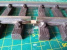
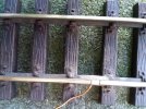
I use an isolated section of rail embedded into the rail by cutting out the rail-head but retaining the base of the rail. The isolated section is around 1/4 inch long. It is secured with an epoxy adhesive.
I fitted several of these on my railway and they have been 100% reliable. Their cleanliness is exactly the same as the running rail, which is logical, How could they be any different?

I use them to activate either opto-isolators or miniature relays.

Metal wheels can trigger them at slow speeds but primarily they are activated by the track voltage within the chassis (locomotive or rolling stock with power pick-ups on 2 axles.)

They are very discreet, reliable and maintenance-free.

Alan
 

Attachments

  • Cut in Rail for insert.jpg
    Cut in Rail for insert.jpg
    792.6 KB · Views: 0
  • Track insert.jpg
    Track insert.jpg
    513.7 KB · Views: 0

PhilP

G Scale, 7/8th's, Electronics
5 Jun 2013
33,561
3,521
Nottingham
Best answers
0
Country flag
With a gap that long, how can a wheel alone trigger? Perhaps 2 axles in a metal sideframe?

Greg
I 'think' there is a detector-wire, attached to the 'bit' epoxied in the gap? :wondering:

I think we need a little clarification? - Well, I do..

PhilP
 

AlanL

Registered
1 Mar 2016
146
19
Northampton
Best answers
0
Country flag
Sorry I was a little short of detail with the connections.

I use a short length of solid wire to support the insert while the epoxy is setting. Soldered before gluing, the heat will soften the epoxy. I super-glue a length of styrene square section to the top of the insert. This allows the insert to be aligned lengthwise with the rails and also sets the height of the insert. The solid wire is bent in position so that it supports the insert from moving (rotating) until the epoxy sets. Black heat-shrink disguises the solid wire.

The insert is connected to a photoisolator via a resistor and then makes a circuit to the opposite rail. The optoisolator is rated for AC voltage and works with DCC and DC track voltage. Where there are long cable runs, I have used miniature PCB relays. The optoisolators were not working, possibly because of inductance / capacitance problems?

When I first envisaged the circuit, I thought that a metal wheel would bridge the gap between the rail and the insert. It would sometimes but only at slow speeds.

It does work 100% with locomotives and rolling stock with good 2-axle pick-ups and lights.

When the first wheel (with track pick-up) of the rolling stock or locomotive, touches the insert, it applies voltage to the insert via it's internal circuit from the other axle /axles (with track pick-ups)

With the Zimo MX 20 application 1/4 inch of insert will be okay depending on your running speed of the trains. With a rough calculation, I estimate that my trains take around 25 milliseconds to traverse the insert. My relays have a response time of less than 10 milliseconds and the optoisolators are around 7 milliseconds.

Of course you could use full size track inserts connected with insulated rail-joiners and the length of the insert would then be limited by the rail-joiner.

If only I knew about these decoders 4 years ago :envy::envy::envy:

Alan
 
8 Mar 2014
7,806
972
San Diego
Country
Armenia
www.elmassian.com
Best answers
0
Country flag
OK, so the insert is metal or plastic or epoxy? Still unclear. It seems the insert must be conductive.

I fully appreciate and applaud that you have actually calculated the triggering times, great. Clearly it must work well!

Greg
 

Derailed

Registered
12 Nov 2019
49
2
Lansing, KS
Best answers
0
Country flag
Thank you. A side photo of the filled portion would be awesome.
For now, I may use a 10153. I figure a 3" sensing section should be plenty if 1/4" works.
 

AlanL

Registered
1 Mar 2016
146
19
Northampton
Best answers
0
Country flag
The insert that I use is normal rail. I start by sawing off the horizontal base of the rail, but but leaving it's length to allow the insert to be held while soldering. Then drill a small hole 1/8 inch from the end. Solder the short length of solid wire using the hole for location/anchorage. I have used various wire gauges for the wire. Finally the insert is cut to it's final length of about 1/4 inch.

The timing calculation was rough mental arithmetic of time divided by distance. I based it on a train covering 10 inches per second. Therefore it would travel forty 1/4 inches per 1000 milliseconds = 25 milliseconds. A very rounded number!

I have 12 of these inserts on my layout to trigger signals and the level-crossing lights, some are 'on' triggers and then the signal resets with a timer. Some signals have an 'on' trigger and an 'off' trigger where station stops are involved and timing a signal to reset would not work.

The inserts are hard to spot, unless you know where to look.

The inserts have no contacts or components to fail.

Locomotives do not require magnets to be fitted, any loco will trigger the circuits.

Alan
 

Attachments

  • train detection insert.jpg
    train detection insert.jpg
    548.2 KB · Views: 0

Derailed

Registered
12 Nov 2019
49
2
Lansing, KS
Best answers
0
Country flag
Another question. Can the decoder be set to ignore the input signal from the reed switch? So if I normally have an automated circuit that always sets the turnout to the right as a train approaches, can I turn that off and set it to manual only, so the train would not throw the turnout and just go straight instead? Not just once but everytime it comes around, it would ignore the reed a proceed straight until I reactivated the input?
 

AlanL

Registered
1 Mar 2016
146
19
Northampton
Best answers
0
Country flag
I would think that you just need an extra switch in parallel with your reed switch. It could be a reed switch or a toggle switch, the important thing would be the quality of the contacts for the low current requirement and, depending on the location of the additional switch if it needs to be weather-proof. If you are already using reed switches then why not use a reed switch to disable the loco-operated reed switch?
Alan
 

Derailed

Registered
12 Nov 2019
49
2
Lansing, KS
Best answers
0
Country flag
I bought an Mx820D to test. I cannot get it to work. Either with the inputs or the cab. I am using an NCE Procab. I am pretty sure it is wired properly to my test track. I have each of the input wires connected to an isolated section of track. I downloaded the manual. NCE is pretty simple as to how to program and use accessory decoders. I tried connecting my computer to the NCE system to use DecoderPro to try and program it but the NCE serial port doesn't seem to work. Any ideas as to how to get this thing working would be much appreciated.
 

phils2um

Phil S
11 Sep 2015
1,522
423
Ann Arbor, Michigan
Country
United-States
Best answers
0
Country flag
A silly question - you are using a conductive wheelset for testing and not a wagon with plastic wheels correct?
 
8 Mar 2014
7,806
972
San Diego
Country
Armenia
www.elmassian.com
Best answers
0
Country flag
You need to get the right drivers for the NCE serial port.

Here's help:

Greg
 

Derailed

Registered
12 Nov 2019
49
2
Lansing, KS
Best answers
0
Country flag
Phil - Yes. I am using a car with LGB Metal BB wheels powering a lamp and a railbroom. So it should cause a voltage drop.
 

Derailed

Registered
12 Nov 2019
49
2
Lansing, KS
Best answers
0
Country flag
Greg, Thank you. I will try it.
It looks like Silabser updated the code. It already has the 12 in those two lines.
 
Last edited: