XLS Massoth Decoder and Massoth 8414002 Auto Uncoupler

frankando12

Registered
15 Jul 2011
192
1
Best answers
0
Country flag
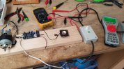
I am trying to connect 2x Uncoupler,s to an old LGB Tank Loco one each end . I have connected one to Function 3 and one to Function 4 can not get either to work,
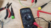
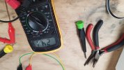
they did work but after multiple tries when I bench tested them, that was before I installed them in the Loco. The one on Function 4 dose work occasionally when Function 4 is pressed . I have increased the input DC Volatage to 24v. The lights slightly blink when F 4 is pressed. The manual shows F4 is for Uncoupler . I have attached a statement form page 12 of the manual which I don't understand . Could some one help me . Thanks Frank
 

Attachments

  • 20190314_152042.jpg
    20190314_152042.jpg
    285.2 KB · Views: 0
Last edited:

idlemarvel

Neither idle nor a marvel
13 Jul 2015
3,136
801
Ascot
Country
Mars
Best answers
0
Country flag
The words are a bit cryptic but I assume they mean you can't use the screw connections for A4 if you have plugged the uncoupler into the A4 uncoupler socket, and don't dim the output to A4 (CV 112 controls A3 and A4 in this respect if you have a newer XLS).

You have connected one uncoupler (the "A4" one) to the provided socket on the upper side of the XLS decoder, yes?

How have you connected the "A3" uncoupler?

When you tried them on the bench, how were they connected? To the same decoder?

The only problem I had with uncouplers was not enough track voltage, 19v was not enough to trigger them consistently, 21v was.

EDIT: FYI you can connect both uncouplers to the same output if you want. You can get a "splitter" cable for this.
 

mibema

Registered
26 Jun 2013
40
1
61
Rhein-Neckar
Best answers
0
Well, it means use either the socket or the screw connection, because they are in parallel. In the socket there are also DEC+ and DEC- .

If you use FA4 for a simple lamp or LED, you can connect it either to the socket, using DEC+ and the FA4 pin (DEC- is not used), OR connect to the screw conector and use DEC+ also from there. You may dimm it to the Lamp-voltage you need.

If you use it for an uncoupler, plug it into the socket, and leave the screw connector free. Also do not dimm the FA4 output, because it will modulate it by PWM and the uncoupler will act up and down....

uncouplers allways need full voltage, as Dave stated. The actual series is much more stable.

make sure you use parallel-mode for DCC, not serial ! otherwise it will blink !

regards,

Michael
 
Last edited:

frankando12

Registered
15 Jul 2011
192
1
Best answers
0
Country flag
Hi Michael and Dave Thanks for your help I bench tested the two uncouplers with the same A4 function button . They both worked but still had trouble with pressing the button multiple times . Did increase the Voltage from 20v-22v but that had no effect, I am using a Regulated power source. I am measuring the voltage with a multi meter and not sure that I am getting the correct reading on the voltage. I am now using 24v to the central station now am hesitant about increasing it more . Thanks again for your Help. Frank
 

PhilP

G Scale, 7/8th's, Electronics
5 Jun 2013
33,455
3,504
Nottingham
Best answers
0
Country flag
The 'common' (as Greg says, usually blue) labelled 'Dec +'
How new is your XLS decoder? - This, and the software revision, may have a bearing on things.
 

idlemarvel

Neither idle nor a marvel
13 Jul 2015
3,136
801
Ascot
Country
Mars
Best answers
0
Country flag
Hi Michael and Dave Thanks for your help I bench tested the two uncouplers with the same A4 function button . They both worked but still had trouble with pressing the button multiple times . Did increase the Voltage from 20v-22v but that had no effect, I am using a Regulated power source. I am measuring the voltage with a multi meter and not sure that I am getting the correct reading on the voltage. I am now using 24v to the central station now am hesitant about increasing it more . Thanks again for your Help. Frank
I would have thought 24v (DC?) to central station would be enough. On my system there is about 3v drop once it has been though the central station and decoder etc. In other words the max DC voltage presented by the decoder is about 3v less than input to the central station. As Greg Elmassian Greg Elmassian and PhilP PhilP said make sure you measure your voltage to A4 using the correct pins.
 

frankando12

Registered
15 Jul 2011
192
1
Best answers
0
Country flag
1q
No offense, but are you measuring the function output referenced to the common (usually blue)?

Also did you measure with nothing connected?

Greg
Hi Greg
What dose (usually blue) mean. I have not measured the A4 terminal with a Multimeter but will try that when I get home in a few days . I will have to pull the Uncoupler back out and bench test them again. I will probably connect both to the A4 function as I have run out of Function outputs. Thanks for your help
 
8 Mar 2014
7,806
972
San Diego
Country
Armenia
www.elmassian.com
Best answers
0
Country flag
Your post #4 says you were measuring voltage.

So, I was assuming you were testing the voltage applied to the uncoupler.

you fixed on "usually blue", but you did not figure out "common".... there is always a common for function outputs. This is normally plus... but it will be called "common", or it should be if anyone is following any standards at all.

So, what did you measure in post #4? Put your multimeter on DC, put the minus probe on the function output (A4) and the plus probe on the common / (usually blue) / + ...

In the manual I looked at, the text calls it +22v COMMON FOR A1...A4... the board itself has a DEC+ on it (very poor documentation, the manual text does not match the board, no excuse)

Greg
 

Dan

Registered
28 Jan 2010
652
51
Eastern MA, USA
Best answers
0
Country flag
I would question what the output of the wired function is. I know what a Zimo decoder does and has this issue.
To reduce the voltage on a function key on a Zimo decoder the decoder used timed pulses. the lower the voltage, the shorter the pulse for on time.
Servos need the full regulated voltage to operate properly as do relays, so I turn off the voltage regulation on my Zimo decoder and then tie servos/relays to a 'pure' regulated supply. (I use the LM7805)
LGB has function keys paired for voltage adjustment on their decoders and I assume they do pulse output for control also.
 

idlemarvel

Neither idle nor a marvel
13 Jul 2015
3,136
801
Ascot
Country
Mars
Best answers
0
Country flag
I would question what the output of the wired function is. I know what a Zimo decoder does and has this issue.
To reduce the voltage on a function key on a Zimo decoder the decoder used timed pulses. the lower the voltage, the shorter the pulse for on time.
Servos need the full regulated voltage to operate properly as do relays, so I turn off the voltage regulation on my Zimo decoder and then tie servos/relays to a 'pure' regulated supply. (I use the LM7805)
LGB has function keys paired for voltage adjustment on their decoders and I assume they do pulse output for control also.
The massoth uncoupler just takes full track voltage, no need for pulse output or servo settings, all that is done in the circuitry inside the uncoupler.
 

frankando12

Registered
15 Jul 2011
192
1
Best answers
0
Country flag
Hi Greg and All
Tested the voltage on A4 as suggested found that to be too high 28v measured on the multimeter DC . There seems be no voltage drop from what goes into the Central Station and what comes out of the A4 function in fact the voltage rises . I am using a 5 amp Regulatated power supply for my Power sourse . I have reduced the voltage input on the Power supply to 20.5 the lowest I can put it down to. The multimeter still reads higher at A4 than 20190321_121428.jpg at the input to the Central Station. The manual for the Uncoupler shows a voltage of 16-22 DCV required to operate the Uncoupler . The manual for the Decoder shows Setting CV112 to 32 gives full track voltage 24v can this CV be changed to a lower voltage . I have attached some photos to show how I am testing the A4 function . Also I hope the Uncoupler has some protection for over voltage .
Thanks Frank
 

Attachments

  • 20190321_121320.jpg
    20190321_121320.jpg
    373.6 KB · Views: 0
  • 20190321_121333.jpg
    20190321_121333.jpg
    310.2 KB · Views: 0
  • 20190321_121348.jpg
    20190321_121348.jpg
    310.6 KB · Views: 0
8 Mar 2014
7,806
972
San Diego
Country
Armenia
www.elmassian.com
Best answers
0
Country flag
The meter shows 24.1 volts... so is the 28v referenced above a mistake?

At low current (like the minute current of a volt meter) it will basically be rectified track voltage.

it's impossible that the +DEC is higher than the track voltage rectified, and I'm pretty sure never higher than the input DC voltage.

Something is strange.

In any case, what voltage do you think the uncoupler wants? The uncoupler manual specifies the connection.

There are 3 wires from the uncoupler... one goes to DEC+, one goes to ground GND and the last goes to A4.... voltage on this line DOES NOT MATTER, all I was after was the voltage goes on and off with the function key to toggle A4.

How did you wire the uncoupler, please specify all 3 wires...

greg
 

frankando12

Registered
15 Jul 2011
192
1
Best answers
0
Country flag
The meter shows 24.1 volts... so is the 28v referenced above a mistake?

At low current (like the minute current of a volt meter) it will basically be rectified track voltage.

it's impossible that the +DEC is higher than the track voltage rectified, and I'm pretty sure never higher than the input DC voltage.

Something is strange.

In any case, what voltage do you think the uncoupler wants? The uncoupler manual specifies the connection.

There are 3 wires from the uncoupler... one goes to DEC+, one goes to ground GND and the last goes to A4.... voltage on this line DOES NOT MATTER, all I was after was the voltage goes on and off with the function key to toggle A4.

How did you wire the uncoupler, please specify all 3 wires...

greg
Hi Greg . 28DCv was what I measured when I first checked the A4 Output before I lowered the Input Voltage. The input voltage now shows 20.2 voltes .
The meter shows 24.1 volts... so is the 28v referenced above a mistake?

At low current (like the minute current of a volt meter) it will basically be rectified track voltage.

it's impossible that the +DEC is higher than the track voltage rectified, and I'm pretty sure never higher than the input DC voltage.

Something is strange.

In any case, what voltage do you think the uncoupler wants? The uncoupler manual specifies the connection.

There are 3 wires from the uncoupler... one goes to DEC+, one goes to ground GND and the last goes to A4.... voltage on this line DOES NOT MATTER, all I was after was the voltage goes on and off with the function key to toggle A4.

How did you wire the uncoupler, please specify all 3 wires...

greg
Hi Greg
The 28DCV was what the A4 showed when I first connected the Multimeter before I lowered the Input voltage . Input voltage is now 20.5 Voltes . Can I Change the CV to get the 22DCV required for the Uncoupler, it does say in the manual not to Dim the Function Outlet , I can not lower the input voltage any further .
Also I am sure I have hooked up the wiring right Red to DC+ Black to DC- Brown to A4 function outlet . I have not removed the Uncouplers from the loco yet bit of job to do that . I did bench test the Uncouplers before I installed them and after installation and they did work although intermittently . I did notice a Post that stated that stated the volatage was raised to make the Function Button work , that is why I raised the voltage thinking that was the reason for the Button working intermittently . I have changed all lights to LED and they are all working full track voltage using Resistors .
Thanks for your help Greg it is much Appreciated.
 
D

Deleted member 4232

Guest
Moved
 
Last edited by a moderator:
8 Mar 2014
7,806
972
San Diego
Country
Armenia
www.elmassian.com
Best answers
0
Country flag
John, if the decoder output is set to full (A4), my understanding there is no PWM, since it is full on when enabled.

Is this correct? You seem to have implied that it is always PWM....

Greg
 

frankando12

Registered
15 Jul 2011
192
1
Best answers
0
Country flag
Thanks John ,
A4 function dose work get a response with a push of the Button . Really appreciate your help will test Dec+ and Dec- in the morning .
 
D

Deleted member 4232

Guest
Moved
 
Last edited by a moderator: