You are using an out of date browser. It may not display this or other websites correctly.
You should upgrade or use an alternative browser.
You should upgrade or use an alternative browser.
With apologies.
- Thread starter Sarah Winfield
- Start date

Sarah Winfield
Registered
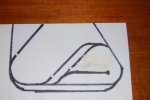
Sorry but I'm messing this up. The picture shows the second reverse loop.
My first R.L. partly shown on the left is now almost operational.
The 2nd loop starts with a single track coming off my main line on the upper right and splits into 2 parallel tracks before re-joining the main line down at the bottom of the picture.
You can see my breaks before the lower points. My question is:-
Can I simply put in isolating joiners on the single curved track or do I need them on both tracks after the point at the top please?
Thanks and again my apologies.
Sarah Winfield
Rhinochugger
Retired Oik
I think the forum is being naughty again today - try after tomorrow's updateI don't think your picture posted correctly, Sarah - it is just showing an image number, no actual pic.....
Jon.

Sarah Winfield
Registered
All:
If you click on the DSC_0213.JPG above the picture will open in another tab..
Sarah:
Yes you can have your upper common track..
BUT
A reverse loop section MUST be long enough to accommodate your longest train.. - You might be better moving your lower-right isolated joiners to below the point?
Depends on how long your trains will be, and the scale of your plan..
So, isolated joiners on the outside of the points (nearest the main-line), and you can use a single DPST switch for all of this section, if the joiners are as above.
Sarah Winfield
Registered
Thank you PhilP.
The right hand track in my double reverse loop is 5' long. I don't possess any bogie coaches only 4 wheelers'. Similarly with my freight wagons, so I imagine my longest train will be about 4' long i.e. locomotive plus 3 coaches or 4 wagons.
When you say "upper common track" are you referring to the single curve after the point at the top of the picture please the one between the 2 points?
If so, I only need to isolate this one curve for both tracks in my reverse loop? That would be good.
SW
Sarah Winfield
Registered
Can I get away with just isolating the top curve before the point which gives me my two tracks or do I have to isolate both track after that point, please?
I don't think I am explaining myself very well am I?
I'll mark up another sketch tomorrow.
Sorry for any confusion.
SW.
I don't think I am explaining myself very well am I?
I'll mark up another sketch tomorrow.
Sorry for any confusion.
SW.
Gavin Sowry
Garden Railroader and Raconteur
I don't think I am explaining myself very well am I?
I'll mark up another sketch tomorrow.
Sorry for any confusion.
SW.
We really need to see the entire layout, because there is a difference between continuous loops, and end to end.
As drawn, we can't see the continuity (but we believe it is there).
Greg Elmassian
Guest
assuming the two tracks at the top right and top left that go off the page connect somewhere,
and assuming the track that starts at bottom left and goes up and to the right is a siding that ends without connecting to anything,
Then you are missing an insulator in the "top" reverse loop section
and you are missing an insulator in the lower reverse loop section
and you should probably move the insulator in the lower section before the switch for the siding.
Sarah... when you were given a nice diagram showing the insulators where they were... We seem to have gone backwards in terms of understanding. Basically you erased insulators that were necessary. What's up?
Greg
Last edited:
Sarah Winfield
Registered
I keep apologising for my lack of understanding and believe me they are genuine.
Ignoring the rest of my layout (please), I have attached 2 new pictures.
The first shows breaks at the top of both sloping tracks. Thus isolating 4 rails, two on each track.
The second shows I have reconnected those and put a break (on two rails) at the top of the curved track before joining the mainline again.
My question is, will I have any electrical issues if I choose the second over the first. please?
Thanks,
Sarah Winfield
Neil Robinson
Registered
I keep apologising for my lack of understanding and believe me they are genuine.
Ignoring the rest of my layout (please), I have attached 2 new pictures.
The first shows breaks at the top of both sloping tracks. Thus isolating 4 rails, two on each track.
The second shows I have reconnected those and put a break (on two rails) at the top of the curved track before joining the mainline again.
My question is, will I have any electrical issues if I choose the second over the first. please?
Thanks,
Sarah WinfieldView attachment 239436View attachment 239437
Sarah, both would work. You'd need two DPDT switches for the first, one for each section between the isolators. However you'd only need one switch if you chose the second proposal. The downside of the second is that it wouldn't work if two trains were to depart the loops simultaneously. With DCC on your proposal this is possible with the trains running in opposite directions but only if you go for the first proposal.
Paradise
Registered
A full picture of the layout would help people understand but I think the two upper left hand tracks are another return loop and the right hand upper track is for roundy roundy on the outside. It runs into the middle of the upper return loop. Unless Sarah has changed things more than I think. 
Sarah Winfield
Registered
Thank you Neil.
Just what I wanted to know. I'll opt for the second of my proposals with just the one DPDT switch .
I think I can now get on with wiring the switch to the main line where I will pick up the power for the return loop.
Sarah Winfield
Just what I wanted to know. I'll opt for the second of my proposals with just the one DPDT switch .
I think I can now get on with wiring the switch to the main line where I will pick up the power for the return loop.
Sarah Winfield
Greg Elmassian
Guest
A little more help.
The first of the new pictures will work and it can work with a single toggle switch serving both insulated sections or 2 toggles for independent control.
The second picture can ONLY work with a single toggle controlling all, since you do NOT have 2 independent sections but just one.
On both drawings though, I would move the insulator on the "inner" reversing section down to include the lower switch.
Otherwise your "inner" reversing loop might be too short. Including the spur makes no difference either way, in the larger picture.
Sarah, the key here is that each "reversing section" must be TOTALLY isolated from the "main".... when you just had one end insulated, the other was still part of the main. Trying to reverse would have caused an instant short.
Greg
Sarah Winfield
Registered
In an effort to reduce the number of rails I need to cut the isolating joiners on my insulated rails inside my loop are staggered by one track length, about 300mm. I.E one side isolating joiner is 300 mm from the other.
Is it necessary to have the isolating joiners opposite one another please?
Thanks,
SW
Is it necessary to have the isolating joiners opposite one another please?
Thanks,
SW
Neil Robinson
Registered
Is it necessary to have the isolating joiners opposite one another please?
Thanks,
SW
No.
However a train should be completely outside or completely inside the isolated section(s) when the switch(es) operate. Staggering the insulated joiners would probably reduce the effective length of the isolated section(s) and therefore reduce the maximum size of trains.
NO. Actually depending on how the isolators are placed at each end of the loop a short situation could be created! BEST TO HAVE THEM PARALELL AT EACH END OF THE LOOP PREFERABLY AT THE POINTS.No.
However a train should be completely outside or completely inside the isolated section(s) when the switch(es) operate. Staggering the insulated joiners would probably reduce the effective length of the isolated section(s) and therefore reduce the maximum size of trains.
Greg Elmassian
Guest
Actually, since you set the polarity FIRST before entering the "loop" there is no possibility of a short.
Likewise, since you then set the polarity BEFORE leaving the loop there is no possibility of a short.
Of course this depends on the train fitting entirely within the loop as stated ad nauseum.
I'd say that Neil's statement is most accurate, but staggering a few inches is not much length lost.
It would be helpful Sarah to give us your idea of a maximum train length as compared to your shortest "loop" (minimum distance between insulators)
The better and more constrained the questions, the better the answers.
Greg
Similar threads
- Replies
- 29
- Views
- 935
- Replies
- 3
- Views
- 531