Why so much electronics for a DC Locomotive?

Airbuspilot

Registered
25 May 2021
247
6
74
Cyprus
Best answers
0
Country flag
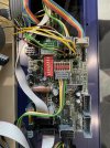
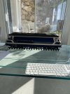
Following on from my previous thread. We have two other DC locos, I cannot identify the one in the picture below so cannot find documentation, however for once it proved very easy to dismantle. There are three circuit boards inside, one large and two small, there is no speaker so I assume a non sound board.

I find it strange that a pure DC loco needs so much electronics, it goes forward and back and the lights work with direction none of which is demanding electronically for a DC motor.

I have pictures of the boards, what do the DIP switches do?

I assume control is no different to my old Hornby train set, I could control voltage but nothing else. With my previous post - when the power was applied the engine started there were compressed air sounds, doors closed and the train moved when the driver was ready. In this case I could imagine some electronic circuitry would be required but why so much for this loco?

Is varying voltage the limit of control with a DC loco of this type?

Robin


Engine.JPG

MOB serial no 20420 - 6 white dots

Big board.JPGSmall board.JPG
 

Software Tools

Registered
18 Jan 2013
309
55
Sydney, Australia
Best answers
0
Country flag
I find it strange that a pure DC loco needs so much electronics
Your LGB 20420 (MOB Ge 4/4) is an MTS (DCC) ready loco. It can be fairly easily fitted with a MTS/DCC decode for digital control. When a MTS/DCC decoder is fitted PCB switch positions need to be changed, as per the user guide.

As far as DC only operation is concerned, the circuit boards control the lighting configuration and also regulate the track voltage down to ~5V for the incandescent and LED lighting.

I assume control is no different to my old Hornby train set, I could control voltage but nothing else.
Basically, yes..... but the lights should come on brightly before the loco starts to move, depending on direction of travel etc.

The early LGB locos had simple directional lighting that varied in brightness with speed but nothing else, but over time model rail customers have asked for more realism, so the manufacturers, including LGB, have incorporates a lot more electronics to satisfy that market demand.

You can find the user manual for your 20420 here....https://www.lgb-trains.com/lib/manuals/en/item/idx20693600.html
 
Last edited:
  • Like
Reactions: 1 user

Zerogee

Clencher's Bogleman
25 Oct 2009
17,353
1,723
North Essex
Best answers
0
Country flag
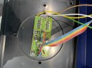
Your loco has been DCC-chipped, either at the factory or as an after-market conversion.... that second picture (I assume there are two identical boards of that type in the loco?) is an early LGB DCC decoder, a 55020, which is plugged into the main board. This is why the grey block of six DIP switches are all set to "off".
The red block of 8 switches serve other purposes, I don't know this particular model so can't say exactly what.

Because of the limited power-handling of the 55020 decoder, two-motor LGB locos required a pair of them, one for each motor.

So you actually have a DCC loco there, of course it will still run perfectly happily on DC analogue as you're using it at the moment. :)

Does the loco have a little round gold sticker somewhere underneath? If so, that will give you its year of manufacture - the first and last of the six digits on the sticker correspond to the year, eg: 9xxxx8 would be a loco built in 1998, and 0xxxx2 would be a 2002 model.

Jon.
 

Rhinochugger

Retired Oik
27 Oct 2009
36,768
4,243
North West Norfolk
Best answers
0
Country flag
I suspect that once you start with a little bit of electronics, for example to give a reduced, constant voltage, directional lighting, then it becomes a bit like medication, and it just self-multiplies.

While I can see the need for the basics, there are quite a few locos that I've worked on where, like our friend who started the thread, I've just asked why?

Smoke and sound are next, then the need to reduce the spaghetti of wiring with a couple of boards and shorter spaghetti etc etc etc :rock::rock::rock::rock::rock:
 

Airbuspilot

Registered
25 May 2021
247
6
74
Cyprus
Best answers
0
Country flag
Thanks very much. If its DCC ready thats thats great news, we have another which is possibly the same.
I will look for a suitable decoder.

For some reason the link doesn't work but I found the info anyway.

Robin
Your loco has been DCC-chipped, either at the factory or as an after-market conversion.... that second picture (I assume there are two identical boards of that type in the loco?) is an early LGB DCC decoder, a 55020, which is plugged into the main board. This is why the grey block of six DIP switches are all set to "off".
The red block of 8 switches serve other purposes, I don't know this particular model so can't say exactly what.

Because of the limited power-handling of the 55020 decoder, two-motor LGB locos required a pair of them, one for each motor.

So you actually have a DCC loco there, of course it will still run perfectly happily on DC analogue as you're using it at the moment. :)

Does the loco have a little round gold sticker somewhere underneath? If so, that will give you its year of manufacture - the first and last of the six digits on the sticker correspond to the year, eg: 9xxxx8 would be a loco built in 1998, and 0xxxx2 would be a 2002 model.

Jon.
Hi Jon

Correct two decoders, the second was difficult to photograph. I will take it over to my friends track this afternoon and try it on the programming track. It was bought assuming it was DCC but then for some reason decided it was DC only, possibly the decoders are not working. I came into this project at the half way point so am still on the learning curve.

There are no gold stickers visible but one of the motor blocks has a plastic plate covering something and it obscures the LGB data so it could be there. Not sure what is underneath but I will try to remove it.

Robin
 

PhilP

G Scale, 7/8th's, Electronics
5 Jun 2013
33,588
3,524
Nottingham
Best answers
0
Country flag
The big circuit board, would have been the original (assuming the loco was initially supplied analogue).
As has been said, two decoders (one for each motor). This is all fairly old-tech (especially the decoders) so a lot of 'bits' needed, to do some quite simple tasks. - Today, it could all the be combined into a smaller number, of smaller components. :nerd:

Part of the problem (for the manufacturers) is that the Buhler motors are quite efficient, and will start turning at 2-3V. But the electronics needs 5-6V in order to wake it up, especially if you want the loco to go through an 'engine-start' sequence, before moving off.

So, electronics to convert whatever is on the track to dc.. Then to stop power getting to the motor(s) immediately.. Then to regulate the supply for the lights.. Then to decide which lights should be on in each direction..
It soon mounts up..

Oh! You also need to wire the loco, in a way that makes it a little easier, to install a decoder, as well!

It does not look to have sound..
The speaker would normally be mounted, where the decoder is. - The round outline, and mounting points moulded into the chassis, are the give-away.
On a loco of this vintage, there would be a pair of blue (but not always) wires, plugged to the board, which connect to the speaker.

The yellow, white, brown, green ribbon cables are from the motor-blocks. The bank of dip-switches are 'off' and the individual yellow, white, brown, green wires take track-power to the decoders, and Motor power back into the loco.
The multicoloured ribbon cable, gives DCC control of the lighting etc.

Have fun, on your friends track!

PhilP.
 

Zerogee

Clencher's Bogleman
25 Oct 2009
17,353
1,723
North Essex
Best answers
0
Country flag
.......

Hi Jon

Correct two decoders, the second was difficult to photograph. I will take it over to my friends track this afternoon and try it on the programming track. It was bought assuming it was DCC but then for some reason decided it was DC only, possibly the decoders are not working. I came into this project at the half way point so am still on the learning curve.

There are no gold stickers visible but one of the motor blocks has a plastic plate covering something and it obscures the LGB data so it could be there. Not sure what is underneath but I will try to remove it.

Robin

If one or both of the 55020 decoders was not working, then I would expect the loco to not function at all, even on DC - when a DCC loco is run on analogue power, the control is still being done by the decoders, they are just responding to the DC power rather than a DCC signal. The fact that the loco runs happily on DC suggests to me that the decoders, although of old design, are probably working fine. To return the loco to pure analogue only (if you wanted to, for some reason), you'd need to remove the decoders and their wiring altogether and set the six DIP switches back to "on".

I reckon you'll find that the loco will respond to DCC on your friend's track, once you've determined what loco address it is set to (read the value in CV1 on the programming track).

If you ever wanted to update the loco a little bit, or if one of the old 55020s ever does become troublesome, then you can easily replace the pair of them with a single more powerful decoder - for example, a Massoth XL (or even an XLS if you wanted to add sound at the same time).

Jon.
 

Airbuspilot

Registered
25 May 2021
247
6
74
Cyprus
Best answers
0
Country flag
Gentlemen you are correct, it is DCC. I could read its address as no 1 on the programming track and various CV’s. CV 29 read 4, trying to run the engine on the main was unresponsive.

I changed CV 29 to 6 and the lights worked but still no movement on the main track.

The engine runs perfectly on DC so presumably I need to switch ON the DCC in some way?
 

PhilP

G Scale, 7/8th's, Electronics
5 Jun 2013
33,588
3,524
Nottingham
Best answers
0
Country flag
You will need to set the DCC equipment to 14 speed steps, for the 55020 decoders.
 

Airbuspilot

Registered
25 May 2021
247
6
74
Cyprus
Best answers
0
Country flag
I started today with 3 DC locomotives.

I finish today with 1 fully functioning DCC, 1 responding but not functioning with DCC and one definitively DC.

So not a bad day really.

Thanks to every one

Robin
 

Airbuspilot

Registered
25 May 2021
247
6
74
Cyprus
Best answers
0
Country flag
CV 29 set back to 4 but still doesn’t run with DCC command. DC still good.
 

PhilP

G Scale, 7/8th's, Electronics
5 Jun 2013
33,588
3,524
Nottingham
Best answers
0
Country flag
CV29 sets the decoder, but the Central Station (possibly the throttle) need to be set to 14 speed steps for this address..
 

Airbuspilot

Registered
25 May 2021
247
6
74
Cyprus
Best answers
0
Country flag
OK, thanks Phil. I had to leave so I will look at it again in a couple of days.
 

Zerogee

Clencher's Bogleman
25 Oct 2009
17,353
1,723
North Essex
Best answers
0
Country flag
Quick question, Robin - unless I've missed it somewhere in your earlier posts, you haven't mentioned what brand of DCC system your friend has, that you've been trying the loco on? LGB MTS, Massoth, Piko, something else?

Jon.
 

Airbuspilot

Registered
25 May 2021
247
6
74
Cyprus
Best answers
0
Country flag
Quick question, Robin - unless I've missed it somewhere in your earlier posts, you haven't mentioned what brand of DCC system your friend has, that you've been trying the loco on? LGB MTS, Massoth, Piko, something else?

Jon.
We have only LGB with ZIMO MX10 and MX 32 for control.
 

phils2um

Phil S
11 Sep 2015
1,522
423
Ann Arbor, Michigan
Country
United-States
Best answers
0
Country flag
Hi Robin - did you unplug the to pantograph motor connectors and the cab control switches connector from the main board for picture clarity? They are normally plugged into the two multi-pin sockets labelled "PV" and "PH" (Pantograph Vorn (front) and Pantograph Hinten (rear)) and the socket labelled "Schalter" on the main board.

i have a LGB Ge 4/4 III loco of the same vintage that I converted to DCC with a Massoth XLS sound decoder. Mine was analog when I got it and did not come with the old MTS decoder (55020) and MTS motor booster board (55030) factory installed. The MTS motor booster board replaced the second 55020 decoder in some two motor LGB locos.

Your post has prompted me to figure out how to get the pantographs to go up and down with DCC. They worked properly with analog power before I did the digital conversion. Since converting both are up unless I physically lock them in the down position. I do have a Massoth pantograph control board but have been reluctant to install it as a replacement to the original LGB interface board.
 
Last edited:

Airbuspilot

Registered
25 May 2021
247
6
74
Cyprus
Best answers
0
Country flag
Hi Robin - did you unplug the to pantograph motor connectors and the cab control switches connector from the main board for picture clarity? They are normally plugged into the two multi-pin sockets labelled "PV" and "PH" (Pantograph Vorn (front) and Pantograph Hinten (rear)) and the socket labelled "Schalter" on the main board.

i have a LGB Ge 4/4 III loco of the same vintage that I converted to DCC with a Massoth XLS sound decoder. Mine was analog when I got it and did not come with the old MTS decoder (55020) and MTS motor booster board (55030) factory installed. The MTS motor booster board replaced the second 55020 decoder in some two motor LGB locos.

Your post has prompted me to figure out how to get the pantographs to go up and down with DCC. They worked properly with analog power before I did the digital conversion. Since converting both are up unless I physically lock them in the down position. I do have a Massoth pantograph control board but have been reluctant to install it as a replacement to the original LGB interface board.
Hello Phil

Correct, plugs removed for the picture.

We have two of these locos, I was told both were DC but it seems one is DCC and the other most probably DC. I am still at an early stage with both G scale and DCC but it would make sense to convert the DC engine. Probably not the priority at the moment but something for a future project. This engine doesn’t operate Pantographs on DC, something I will check.

Robin
 

phils2um

Phil S
11 Sep 2015
1,522
423
Ann Arbor, Michigan
Country
United-States
Best answers
0
Country flag
Thought I'd give an update on Robin's thread about my LGB Ge 4/4 III pantograph issue since I lamented about it here in post 18. I reloaded the Massoth sound project for this loco into the XLS decoder I had installed last year. After a lot of review of CVs as they existed and what I thought they should be I discovered one of the pantograph controls, that for the front pan over cab I, was assigned to the wrong function key. It was assigned to the ventilator sound function key (F10) by the sound project. The key did lower and raise the front pan when driving in the forward direction. I reassigned the function to the pantograph sound function key (F12) and changed it to work in both directions. I still could not find the issue with the rear pantograph control - It is up all the time unless physically clipped in the down position. This is not much of a problem though as I usually run with cab I, the cab with the driver figure, forward anyway and the rear pan should be up when driving in this direction. Reloading the sound project seems to have corrected another issue I was having with the driving sounds too.

So, thanks Robin for prompting me to pursue this with your question on the Ge 4/4 III. I learned a little more about Massoth XLS sound decoders and their installation in early LGB digital ready locos.