The mechanic
Registered
Hello all,
The new layout is coming on well but.I have a bit of a conundrum.....
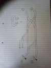
I have attached a rough schematic diagram that shows the track layout (both rails) of my main station. I use LGB standard trackwork. The station limits are joined by two loops that run around the edge of the garden. #1 is linked to #1 and #2 is linked to #2. I feed 12v-18v analogue DC at the ponts shown by the feed symbols.
Now, I know that the cross overs need isolating, but I am asking you kind people, where is the best place to put them in order to avoid additional switching and track power feeds?... I really want to reduce these to the absolute bare minimum thereby having the operation pretty "automatic" and "idiot-proof" (or should I say male Sixty-something-proof?) if at all possible?
Each loop will be operated on an independent "one engine in steam" principle.
I feed the layout via two hand held first-edition Train Engineers ( one per loop) that are commonly fed by a 24v/ 30amp stabilised power supply located indoors. Which is OK when the two loops are running independently, but at some point (no pun intended) I will need to run-round and/or shunt the two sidings. If I am using a common power supply for the TEs, there is short circuit potential at the crossovers where metal wheels can bridge isolating track joints? I am open to using diode-protected section breaks if this is feasible to avoid this scenario (however, my head cannot handle this sort of "electrickery")
I welcome your suggestions and opinions on this
Dave
The new layout is coming on well but.I have a bit of a conundrum.....
I have attached a rough schematic diagram that shows the track layout (both rails) of my main station. I use LGB standard trackwork. The station limits are joined by two loops that run around the edge of the garden. #1 is linked to #1 and #2 is linked to #2. I feed 12v-18v analogue DC at the ponts shown by the feed symbols.
Now, I know that the cross overs need isolating, but I am asking you kind people, where is the best place to put them in order to avoid additional switching and track power feeds?... I really want to reduce these to the absolute bare minimum thereby having the operation pretty "automatic" and "idiot-proof" (or should I say male Sixty-something-proof?) if at all possible?
Each loop will be operated on an independent "one engine in steam" principle.
I feed the layout via two hand held first-edition Train Engineers ( one per loop) that are commonly fed by a 24v/ 30amp stabilised power supply located indoors. Which is OK when the two loops are running independently, but at some point (no pun intended) I will need to run-round and/or shunt the two sidings. If I am using a common power supply for the TEs, there is short circuit potential at the crossovers where metal wheels can bridge isolating track joints? I am open to using diode-protected section breaks if this is feasible to avoid this scenario (however, my head cannot handle this sort of "electrickery")
I welcome your suggestions and opinions on this
Dave
Attachments
Last edited:


