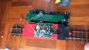
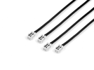
Upgrading an LGB 22802

AusrailQLD

Registered
Country flag
Quick backstory, so I got an LGB 22802.
The 2-6-2 in Green instead of the common Black.

And I found someone selling 23802 Electronic components.
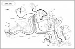
22802_soundwire.JPG23802_soundwire.JPG

To me, I think I should (in theory) be able to use them in my loco.
(And to DCC in future.)

However, I'm not sure about the Chuff sensor wiring.
The 22802 is a 4 cable, where as the newer has 3 wires.

Has anyone converted one of these?
And know which wire goes where?

I know two will be joined together to be a common, but I'm not sure what is what.


Also will the different design of the lead weight be an issue?
I'm not really keen on cutting to make the sound unit fit.
 
Quick backstory, so I got an LGB 22802.
The 2-6-2 in Green instead of the common Black.

And I found someone selling 23802 Electronic components.
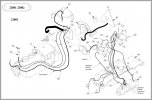
View attachment 295404View attachment 295405

To me, I think I should (in theory) be able to use them in my loco.
(And to DCC in future.)

However, I'm not sure about the Chuff sensor wiring.
The 22802 is a 4 cable, where as the newer has 3 wires.

Has anyone converted one of these?
And know which wire goes where?

I know two will be joined together to be a common, but I'm not sure what is what.


Also will the different design of the lead weight be an issue?
I'm not really keen on cutting to make the sound unit fit.
I'm confused. You indicate that you bought the electronics circuit boards from an LGB 23802, which has sound and DCC Interface Connector for installing a decoder. But then you say the 22802 has a 4 cable......the 22802 has sound but no DCC Interface?

And I've never heard of two, 2-wire configuration for pulse generators installed in an LGB locomotive motor block. Massoth decoders have two pulse generator connectors, 3-pins each, on the XLS DCC sound decoder to be used for certain LGB locomotives that have a double chuff sound.
 
Yes the 22802 has no DCC interface, and a very old analogue only sound card.

If you look at Diagram, for the 22802, Part 77 shows the Chuff Sensor has 2 sets of wires, 4 in total.
Newer Chuff sensor use a 3 wire.

Basically I needed to know which two of the wires to join together to be the common, but unsure what.


Part 107 is the Bell and whistle wires, which I need to do the same.
However, it's much easier to under in terms of converting from 4 to 3 wires.


In an update, I bought the "23802" parts only to discover the main board is a 22801. (not compatible)
So they have to be sent back.

However I did find a German company selling a complete 23802 electronics kit with a chuff sensor included, so I plan to use that.
 
Long over due update.
So I finally got all the parts, and everything is mostly working.

However I'm struggling with the CV
(I'm autistic so I get a little lost)

So I understand that the Sounds are controlled by serial input. (Pressing the F1 button over and over)
Is there a way to get the Massoth decoder to simulate, say pressing F3 once to be the same as F1 three times to activate the smoke?

I did read the Dummies Guide and it said CV 49 effects parallel and serial values, but I'm not sure what else.

I'm using a MRC Prodigy System. (I know there are better ones out there, but this is what I could afford at the time)
 
Installed a Massoth XLS in an early LGB Ge 4/4 III that had a decoder interface board using Aux1 pulses to operate the two pantographs. For what it is worth, I was never able get the Massoth decoder I installed to simulate multiple pulses either. I was using the Massoth decoder programmer and Massoth Service Tool software. I tried various CV settings having to do with pulsed function operation but could not get it to do what I wanted and gave up. I settled on using one or more taps of the function button I mapped to Aux1, F11 in my case, to operate the pantographs. It's somewhat awkward but works for me. The XLS is my sound decoder so I only need the Aux1 pulses to operate the pantographs. One tap raises the rear pan, two in secession raise the front pan, three lowers the rear, and four taps lowers the front. If someone out there knows the secret to Massoth decoder multiple pulse simulation it would be helpful to me too.
 
Is there a way to get the Massoth decoder to simulate, say pressing F3 once to be the same as F1 three times to activate the smoke?
I have an LGB 28002 and have similar issues.

The Massoth L does support "fast pulse" mode. However, the implementation of fast pulse mode is fast, way less than 0.25 seconds per pulse. In my testing, the older pulse interface only registers pulses at least 0.5s apart.

The only decoder that I have found that implements the LGB pulse interface slow enough to work on these older interfaces is the Micron-Dynamics DRIVE-L. Setting CV#49, bit 3 causes the system to correctly map F1-F8 to pulses out A1.

The Zimo MX series large scale decoders also have a pulse setting (CV#112, bit 7), but I only have the newer MS series and the CV map doesn't define that behaviour for the newer decoders. It might work anyway, but I haven't tested it. Also, the Zimo support tech could not confirm for me the pulse rate.


Also, the Massoth implementation is a bit odd. I found that to get pulse mode to function I also have to turn on serial mode mapping for F1, which struck me as a bit silly. There's no necessary connection between using F1-F8 to pulse output A1 (new handset, old loco) and having the decoder recognise serial mode communications (old handset).
 
Last edited:
Sorry, forgot to add the details.

- The Loco is now a LGB 23802 with the original sounds that are Digital Compatible.
- The Decoder is a Massoth eMotion L, with the required Decoder Interface Cable.

- The DCC systems I'm using is a a MRC Prodigy System
With Booster for Large Scale application.

The Sounds are working, when I press F1 the correct numbers of times to activate Bell, whistle and such.
- Press F1 - 1x: Whistle
- Press F1 - 2x: Bell
- Press F1 - 3x: Smoke generator on/off
- Press F1 - 4x: Sound on/off
- Press F1 - 5x: Air pump, slow
- Press F1 - 6x: Brake
- Press F1 - 7x: Coal shoveling
- Press F1 - 8x: Air pump, fast
(You get the idea, - you have to send a Series of 'Pulses')
I just thought maybe there was a way to be able to press Function buttons 1 to 8 to get the same results. Rather than me pressing F1 up to 8 times.

Or at least change the Button from F1 to F2.
(I think it's CV56 I need to change to value of 1, but not 100% sure)

If there is a solution, great, if not, at least it doesn't hurt to ask. :-)
 
(You get the idea, - you have to send a Series of 'Pulses')
I just thought maybe there was a way to be able to press Function buttons 1 to 8 to get the same results. Rather than me pressing F1 up to 8 times.

Or at least change the Button from F1 to F2.
(I think it's CV56 I need to change to value of 1, but not 100% sure)
Enabling CV#49, bit 0 and CV#49, bit 3 will cause F1-F8 to fast-pulse A1. But the pulses are very fast, too fast for some older sound modules to recognise.
 
The only decoder that I have found that implements the LGB pulse interface slow enough to work on these older interfaces is the Micron-Dynamics DRIVE-L. Setting CV 49, bit 4 causes the system to correctly map F1-F8 to pulses out A1.
Thanks for that Andrew, I wonder if Marius' other loco decoders are similarly capable? And, if the pulsed output configuration can be used simultaneously with his SUSI sound decoder? I think he is an occasional visitor to this site. Perhaps he can answer?

As an aside, I'm glad to see his product line both expand and gain the acceptance that it has. I'm quite satisfied with the function and cost of the MD items I've purchased, both directly, and more recently those re-branded by Modell-Land.de. I somewhat regret not having the entrepreneurial spirit to come forward when he was seeking a U.S. distributor a few years ago.
 
Thanks for that Andrew, I wonder if Marius' other loco decoders are similarly capable?
Depends on the model. For example, the DRIVE-M uses CV#49, bit 3 to enable "Marklin Train Bus". The DRIVE-XL supports pulse, but on A8 not A1.
And, if the pulsed output configuration can be used simultaneously with his SUSI sound decoder?
From my conversations with Marius I believe this works fine. You may need to choose the triggers for the SUSI decoder such that they don't interact with the legacy interface.

My wishlist is for the decoders to support ABC. Other than that I've found they have a good feature set.
 
Or at least change the Button from F1 to F2.
(I think it's CV56 I need to change to value of 1, but not 100% sure)
Yes, for Massoth loco decoders setting CV56 = 1 will set F2 to map to the decoder Aux1 output also. You will still need to push it three times but you can give it a separate smoke icon on your controller. The only problem is it will still respond to the F1 key too and you may inadvertently turn it on or off when you try to trigger a sound needing more than three pulses.
 
Last edited:
The only decoder that I have found that implements the LGB pulse interface slow enough to work on these older interfaces is the Micron-Dynamics DRIVE-L. Setting CV 49, bit 4 causes the system to correctly map F1-F8 to pulses out A1.
I should have mentioned that this is a great, and not very expensive solution for AusrailQLD! It will replace AusrailQLD's Massoth decoder without any difficulty and supply the functionality he is looking for.

In my case, with only the two pantographs operated by Aux1, it is not worthwhile for me to swap out my Massoth XLS.
 
Thanks everyone, I have a look at getting a Drive-L Decoder in the future.
In the meantime I will work with what I got.

One last puzzle to solve.
Does anyone know where is the best place to mount the decoder?
Unfortunately the LGB manual doesn't provide any clues.
20221019_082957.jpg

I tried multiple places in the boiler, but the body shell won't fit.
 
No particular experience with that model, but two suggestions just from looking at the picture:
  1. Can you slide it into that recess in front of the existing electronics?
  2. Is there space in the cab where you can hide it?
In either case, you might want to slide some sort of sheath or cover over it if you plan to use the loco outdoors, to protect against stray moisture.
 
Put the chip in the void between the rear of the loco and the cab...under the coal..run the wires across the cab floor..
Me ,I'd ripped the old stuff out..and wire directly to the chip..but that's just me
 
You might (just) be able to mountit vertically against the side of one of the tanks?
Possibly the side the DIP switches are located, but it will be tight..

I am with Mike..
The original Sound would be removed, and replaced with an XLS decoder.

PhilP
 
Might be some be sometime before I'll take action with the XLS decoder replacement.

Considering I spent 10 months converting this old loco to Digital this far.
I'm not 100% keen to scrap all the difficult to obtain electronics just yet. :-(
(I still don't know what I'm going to do with the originals I ripped out that these replaced.)


Also I've have a XLS decoder in another loco and it's proving to be just as difficult.
Which it to also took me 10 months to convert, who knew trying to get these plugs would be the hardest thing.
1666297923391.png

Australia supplier is hopeless when trying to order.
Guess that serves me right for trying to support local businesses.
 
Back
Top Bottom