You are using an out of date browser. It may not display this or other websites correctly.
You should upgrade or use an alternative browser.
You should upgrade or use an alternative browser.
Transmitter battery voltage
- Thread starter WKDOR
- Start date
Rhinochugger
Retired Oik
Mine have all come ready built, and take a 9v PP3 - I haven't had to replace a battery yetTwo questions please:
What is the minimum voltage that will allow a Deltang Tx to function reliably? Where is it specified?
 does that mean I'm not playing with my trains enough ?
From what I have just been reading both the Kit and ready made use a 9v PP9. See specs be,ow.Two questions please:
What is the minimum voltage that will allow a Deltang Tx to function reliably?Where is it specified?
Micron Radio Control : DSM2 Model Railway Controllers
Rhinochugger
Retired Oik
PP3 my dear friend - PP9 is a monsterFrom what I have just been reading both the Kit and ready made use a 9v PP9. See specs be,ow.
Micron Radio Control : DSM2 Model Railway Controllers
www.micronradiocontrol.co.uk

I did wonder!PP3 my dear friend - PP9 is a monster
Greg Elmassian
Guest

WKDOR
Registered
So that wasn't the problem then!
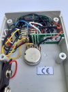
All the locos bound to a particular Deltang TX were having problems. After extensive testing I eventually suspected that the Direction switch wasn't working at all when moved to Down= Reverse. Sure enough when I transferred all the locos to a different TX they worked fine.
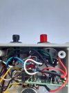
Opening up the faulty one I can see at the top a green cable with a blob of solder that doesn't go anywhere and nearby another blob of solder with connections to the switch. Are they supposed to be connected? Could this be the likely cause of my problem?
All the locos bound to a particular Deltang TX were having problems. After extensive testing I eventually suspected that the Direction switch wasn't working at all when moved to Down= Reverse. Sure enough when I transferred all the locos to a different TX they worked fine.
Opening up the faulty one I can see at the top a green cable with a blob of solder that doesn't go anywhere and nearby another blob of solder with connections to the switch. Are they supposed to be connected? Could this be the likely cause of my problem?
Attachments
I am unable to quote text (again) - Or pull-up the smilies menu.. :-{
First thing I would say:
That! Is not one of my transmitters!!
Disconnect the battery, before fiddling inside there!
Is there any insulation between the circuit board, and the connections on the potentiometer?
How good are you with circuit diagrams? - Here, is a link to the circuit diagram on the Deltang website:
Please note, the resistor values may be different, but the general arrangement will be the same.
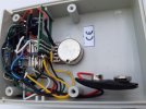
I am having difficulty following the wiring.. Could you take a picture at slightly oblique angle, looking from the 'bottom' of the present picture?
One side of all the switches, a (probably) 470 ohm resistor, and one end of the Speed pot. should all be connected together.
As you look at the pointy end of the pins, with the green board at the BOTTOM:
The bottom row of pins are all negative.
The middle row of pins are all positive.
The TOP row of pins are 'signal' pins, 1 - 7, left to right:
Pin 1 centre contact of Speed control - possibly yellow in your picture?
Pin 2 one of the push buttons - ? not clear.
Pin 3 centre contact of the toggle switch - blue in your picture.
Pin 4 one of the push buttons - possibly green in your picture?
Pin 5 bind button (black switch, next to power button?) - white in your picture (on the left of the picture).
Pin 6 no connection.
Pin 7 no connection.
The more I look at this picture, the more I think the wiring is incorrect. - I may be confusing myself..
PhilP.
First thing I would say:
That! Is not one of my transmitters!!
Disconnect the battery, before fiddling inside there!
Is there any insulation between the circuit board, and the connections on the potentiometer?
How good are you with circuit diagrams? - Here, is a link to the circuit diagram on the Deltang website:
Please note, the resistor values may be different, but the general arrangement will be the same.
I am having difficulty following the wiring.. Could you take a picture at slightly oblique angle, looking from the 'bottom' of the present picture?
One side of all the switches, a (probably) 470 ohm resistor, and one end of the Speed pot. should all be connected together.
As you look at the pointy end of the pins, with the green board at the BOTTOM:
The bottom row of pins are all negative.
The middle row of pins are all positive.
The TOP row of pins are 'signal' pins, 1 - 7, left to right:
Pin 1 centre contact of Speed control - possibly yellow in your picture?
Pin 2 one of the push buttons - ? not clear.
Pin 3 centre contact of the toggle switch - blue in your picture.
Pin 4 one of the push buttons - possibly green in your picture?
Pin 5 bind button (black switch, next to power button?) - white in your picture (on the left of the picture).
Pin 6 no connection.
Pin 7 no connection.
The more I look at this picture, the more I think the wiring is incorrect. - I may be confusing myself..
PhilP.
WKDOR
Registered
Many Thanks for the speeedy and comprehensive response Phil. Yes I confirm that its not yours!
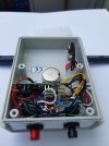
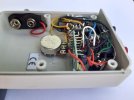
Your wish is my command, new pix:
Your wish is my command, new pix:
I am unable to quote text (again) - Or pull-up the smilies menu.. :-{
First thing I would say:
That! Is not one of my transmitters!!
Disconnect the battery, before fiddling inside there!
Is there any insulation between the circuit board, and the connections on the potentiometer?
How good are you with circuit diagrams? - Here, is a link to the circuit diagram on the Deltang website:
Please note, the resistor values may be different, but the general arrangement will be the same.
I am having difficulty following the wiring.. Could you take a picture at slightly oblique angle, looking from the 'bottom' of the present picture?
One side of all the switches, a (probably) 470 ohm resistor, and one end of the Speed pot. should all be connected together.
As you look at the pointy end of the pins, with the green board at the BOTTOM:
The bottom row of pins are all negative.
The middle row of pins are all positive.
The TOP row of pins are 'signal' pins, 1 - 7, left to right:
Pin 1 centre contact of Speed control - possibly yellow in your picture?
Pin 2 one of the push buttons - ? not clear.
Pin 3 centre contact of the toggle switch - blue in your picture.
Pin 4 one of the push buttons - possibly green in your picture?
Pin 5 bind button (black switch, next to power button?) - white in your picture (on the left of the picture).
Pin 6 no connection.
Pin 7 no connection.
The more I look at this picture, the more I think the wiring is incorrect. - I may be confusing myself..
PhilP.
Attachments

WKDOR
Registered
Yes Phil, see the green wire at centre top of first pic today, filename ending 2221.JPG
Best
Mike
Best
Mike
There are an awful lot of resistors in that transmitter..
Which green wire is not connected? - Top-centre, by any chance??
Read all this through.. You may want to start with the last-line? ")
Right.. Referring to this image:

Is this supposed to be a 'special' (built just for you) to do anything non-standard? - There seem to be pull-up/down resistors all over the place, and unless they are to fine-tune actions, then I do not know why this has been done?
Has the calibration process been done on this transmitter? - It should not make too much difference, but removes one query.
(NOTE: If we remove any resistors etc. re-calibrate before testing).
No names, no pack-drill.. Send me a PM, as to who built this please..
Top of picture, there appears to be a pair of 10k resistors which are wired between the two push-buttons? - The right-hand end of the right-hand resistor appears to either be disconnected, or connected to the opposite (ground/black-wire) on the right-hand switch.
Assuming there is a green-wire from each switch? - One to Pin 2, one to Pin 4.
There seems to be a green wire, from this switch, to the centre of these two resistors?
If you look at the circuit diagram:
These switches should have a ground (negative/black) connection, and a 'signal' wire going to either Pin 2 or Pin 4.. - Anything else is not needed, or incorrect.
I would cut the green wire, at the right-hand switch, which runs to the centre of the two resistors.
I would remove these two resistors, and the short bit of green wire, we have freed from the Right-hand switch.
Toggle switch:
The 470 ohm resistor (connected to top pin of switch) should-be (and appears to be) connected to the ground/negative connection of the left-hand push-button.
There should be an 18k resistor from the top-pin to the bottom-pin of the toggle switch. - This appears correct, on the left of the toggle-switch as we look at it.
There should be two 100k resistors. One from the top, to the middle pin, and one from the middle to the bottom pin. - This appears correct.
From the bottom pin of the toggle switch. There should be a 10k resistor to the red wire going to a pin on the edge of the Tx2 module.
There should also be a 10k resistor, from the right-hand pin of the Speed pot. going back to this pin. - The resistor appears to be in heat-shrink near the connection to the pot. and this wire seems to join correctly to that from the toggle-switch.
Speed control:
I assume the left-hand end is wired (very firmly) to the bottom row of pins of the Tx2 module, and it is this holding it in place?
Right-hand pin we covered, above.
Centre-pin (yellow wire) should go to Pin 1. - This appears correct. There should not be anything else connected to Pin 1.
Whilst we are talking 'yellow wires'.. There appears to be a yellow wire, from the negative (bottom row of pins on the Tx2) going 'somewhere'. - Where does this go?
Bind button:
Should have a ground/negative/black connection, and the white wire to Pin 5. - Appears correct, and you must have bound a Rx to the transmitter.
'Signal' pins on the Tx2 module:
No signal pin (top row of pins) should have more than ONE wire connected.
Battery positive:
This should be wired directly to any of the centre-row of pins. - There should only be ONE connection to the centre-row of pins.
Other 'extra' resistors:
Other than those we have talked about, there appears to be a resistor in the black lead from the Tx2 to the left-hand push-button??
There appears to be a resistor in the black wire continuing from the push-button?? - You can see it below the junction of the two top resistors and the green wire, top-centre of the picture.
From the circuit diagram, there are NO resistors in series along the negative connection between the switches.. - These should be plain-wire connections.
Alternatively:
You may wish to send it to me, and cross my palm with silver?
")
PhilP.
Right.. Referring to this image:
Is this supposed to be a 'special' (built just for you) to do anything non-standard? - There seem to be pull-up/down resistors all over the place, and unless they are to fine-tune actions, then I do not know why this has been done?
Has the calibration process been done on this transmitter? - It should not make too much difference, but removes one query.
(NOTE: If we remove any resistors etc. re-calibrate before testing).
No names, no pack-drill.. Send me a PM, as to who built this please..
Top of picture, there appears to be a pair of 10k resistors which are wired between the two push-buttons? - The right-hand end of the right-hand resistor appears to either be disconnected, or connected to the opposite (ground/black-wire) on the right-hand switch.
Assuming there is a green-wire from each switch? - One to Pin 2, one to Pin 4.
There seems to be a green wire, from this switch, to the centre of these two resistors?
If you look at the circuit diagram:
These switches should have a ground (negative/black) connection, and a 'signal' wire going to either Pin 2 or Pin 4.. - Anything else is not needed, or incorrect.
I would cut the green wire, at the right-hand switch, which runs to the centre of the two resistors.
I would remove these two resistors, and the short bit of green wire, we have freed from the Right-hand switch.
Toggle switch:
The 470 ohm resistor (connected to top pin of switch) should-be (and appears to be) connected to the ground/negative connection of the left-hand push-button.
There should be an 18k resistor from the top-pin to the bottom-pin of the toggle switch. - This appears correct, on the left of the toggle-switch as we look at it.
There should be two 100k resistors. One from the top, to the middle pin, and one from the middle to the bottom pin. - This appears correct.
From the bottom pin of the toggle switch. There should be a 10k resistor to the red wire going to a pin on the edge of the Tx2 module.
There should also be a 10k resistor, from the right-hand pin of the Speed pot. going back to this pin. - The resistor appears to be in heat-shrink near the connection to the pot. and this wire seems to join correctly to that from the toggle-switch.
Speed control:
I assume the left-hand end is wired (very firmly) to the bottom row of pins of the Tx2 module, and it is this holding it in place?
Right-hand pin we covered, above.
Centre-pin (yellow wire) should go to Pin 1. - This appears correct. There should not be anything else connected to Pin 1.
Whilst we are talking 'yellow wires'.. There appears to be a yellow wire, from the negative (bottom row of pins on the Tx2) going 'somewhere'. - Where does this go?
Bind button:
Should have a ground/negative/black connection, and the white wire to Pin 5. - Appears correct, and you must have bound a Rx to the transmitter.
'Signal' pins on the Tx2 module:
No signal pin (top row of pins) should have more than ONE wire connected.
Battery positive:
This should be wired directly to any of the centre-row of pins. - There should only be ONE connection to the centre-row of pins.
Other 'extra' resistors:
Other than those we have talked about, there appears to be a resistor in the black lead from the Tx2 to the left-hand push-button??
There appears to be a resistor in the black wire continuing from the push-button?? - You can see it below the junction of the two top resistors and the green wire, top-centre of the picture.
From the circuit diagram, there are NO resistors in series along the negative connection between the switches.. - These should be plain-wire connections.
Alternatively:
You may wish to send it to me, and cross my palm with silver?
PhilP.
Rhinochugger
Retired Oik
I'd take him up on his offer 
Similar threads
- Replies
- 22
- Views
- 735
- Replies
- 2
- Views
- 394