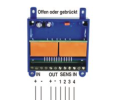
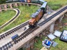
Reverse loop setting up, carn't get it to work. (EDIT things are now up and running, thanks for the suggestions)

Post #10 by Software Tools is the best solution, have you not considered it?

It does not require any civil engineering.

It only requires 1 reversing unit although if you are using sensors to trigger the reversing unit that becomes more complicated. It could be dificult to fit the sensors between the pairs of crossover points.

For ease of installation I would not bother with the sensors. The reverse unit detects the short circuit and instantly flips the polarity. I used my reverse units many years in short circuit mode without any issues.

You can add the opposite crossover without causing any problems, providing that the yellow reversing section is extended to accomodate your trains.

This solution is the same as post #8 in your linked thread, by having the reversing section on a length of the main running loop.

AL
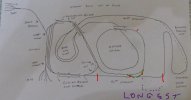

I am considering all options, including not doing anything at all, if that is how it turns out. It initally looked so simple, basically make a couple of diagonal loops in an oval, but I guess I was wrong. :(
 
I am considering all options, including not doing anything at all, if that is how it turns out. It initally looked so simple, basically make a couple of diagonal loops in an oval, but I guess I was wrong. :(
Dir the penny has dropped, you have a loop and an extension to that loop. Where the triangle or reversing needs apply is where you make any joint along the 50ft straight. This effectively creates the triangle.

If you were to put your crossovers as near to the end of the loop you would need to use the loop module in one of the leads to those points and just beyond one if them at the longest length of your longest train. Thus this will work for you. Green new points, red isolations both rails blue length of longest train. Isolations at points where points join each other I think the track leading to and with what is left of the 50ft after points fitted should be long enough for your longest train. Something a,ong these lines has already been suggested. IMG_8686.jpeg
You would not be able to have a set of points on the straight closer to Collings Jcn as there needs to be at least a full train length within changeover section, that being the bit between the isolation sections.
 
I am considering all options, including not doing anything at all, if that is how it turns out. It initally looked so simple, basically make a couple of diagonal loops in an oval, but I guess I was wrong. :(
Reverse loops CAN be quite simple in DCC, but also not depending on the circumstances. There are rules that need to be taken into account. If you dont have metal wheels or lights in coaches then it can be quite short and only the length of the locos, but if you do have lights and metal wheels it needs to be the length of the train otherwise it will not work properly. There's no way around that.

The 50ft straight with 2 crossovers is your best place for it observing the above requirements. dunnyrail dunnyrail 's suggestion allows reversing in both directions, which is ideal. It requires 4 switches, 2 of which will be in the reversing circuit. A single Massoth module with short circuit mode will handle it just fine.
 
dunnyrail dunnyrail is that red mark next to the bridge on the spriral an additional isolation point?

I can see your plan working, if I can figure out where is best to fit the module, I may have a go this weekend to see if it can be started whith the pair of points I have, then install the other pair when finances allow.

BTW I found this on the Massoth Wiki page, maybe something that should be in the instruction manual but isn't.


Maybe of no help to me but at one point I was thinking did I or could I fit an additional sensor track section.
 
Maybe of no help to me but at one point I was thinking did I or could I fit an additional sensor track section.
Yes it is very relevant to your application.

If you are intending to use sensor tracks, then instead of the 3 sets of isolated track sensor sections as shown in the Massoth info, you would need fourth one at the other crossover. The isolation sections on the 50ft straight can be any position on the tracks to give ample length for your trains .

The sensor tracks in the crossover section, (in the Massoth diagram) are wired to terminals 1 and 2 of the reverser unit. The sensors along the straight section are both wired to terminals 3 and 4. With your extra isolating sensor track, I couldn't advise how to wire it, hopefully someone with more experience could advise.

Personally I would just use the reversing module in short circuit mode. It is far simpler especially when you have 4 isolating positions and is guarateed to work first time because it is much easier to wire.:D:D:D


AL
 
with the sensor tracks it's more straight-forward than it looks. All the sensor tracks do is detect the polarity that the isolated track section should have based on the section sensor last touched by the train.

There are only 2 options for polarity - lets call them normal polarity and polarity reversed. in terms of your inputs on the module, you have 2 inputs for each group of sensors because that's all you need electrically.

Probably the easiest way to think if the grouping is:
  • 1 & 2 Main Route Sensor Group - sets normal polarity
  • 3 & 4 Alternative route sensor group - sets reversed polarity

Typically you would see 2 sensors in the main route group and one in the alternative route group.
 
So the state of play/reasembly is as follows.

I have made 2 additional sensor track sections, but the re-install has reached the following...

20250809_124510[1].jpg20250809_124545[1].jpg20250809_124819[1].jpg

So if I have got my head around this the following will apply track breaks/sensor tracks at glass jar (Picture 1) tape measure (Picture 2). There is only one pair of points installed at present, as that's all I have for now. So a dummy straight is positioned to give me and idea of where the second pair they will fit.
So Picture three will be were I put the main + - in/out and a sensor, if I am correct. Then just a case of figuring out what to do when the second pair of points are installed a full parallel in out or just a sensor.
 
Last edited:
1754767162719.png


Based on the the diags above.

  • IN = Track Power
  • OUT = Isolated Section
  • SENSOR IN 1/2 = Cross connect Sensors at Picture 1 Coffee Jar & Picture 2 Expanded measuring tape main body
  • SENSOR IN 3/4 = Cross connect Sensors at picture 3 minimised measuring tape and pretend track junction.
bear in in mind with this diagram, if both points are open, then your longest possible train is about a light loco or you will get a short.

with this in mind, it's probably worth moving the crossovers further apart.
 
bear in in mind with this diagram, if both points are open, then your longest possible train is about a light loco or you will get a short.
I don't think so.

If the reversing section is normal polarity, it will flip as soon as the locomotive crosses from the inner loop on to the outer loop and remain reversed polarity for the whole train to exit the crossover until another train reverts the reversing section to normal polarity.

If the reversing section is reversed, it will match the polarity of the inner loop anyway.

AL
 
Nodrog1826, with your second crossover, have you considered installing it at the left hand side of your inner loop in the same way as your right hand crossover?
It would look a lot better than having a reverse curve crossover, especially on a main line and it will match the other crossover.

There is no reason to have the crossovers close together, it will make no difference.

Your plans for the isolating positions could accomodate 2 long trains!
It is the only the distance between the isolators on the main straight that is relevant

AL
 
Ok, we have success...

20250810_133020.jpg

...that was inspite of the instructions and the illustration not in agreement with each other. So one part down, then work started on fitting the point module.
 
dunnyrail dunnyrail is that red mark next to the bridge on the spriral an additional isolation point?

I can see your plan working, if I can figure out where is best to fit the module, I may have a go this weekend to see if it can be started whith the pair of points I have, then install the other pair when finances allow.

BTW I found this on the Massoth Wiki page, maybe something that should be in the instruction manual but isn't.


Maybe of no help to me but at one point I was thinking did I or could I fit an additional sensor track section.
Yes it is. Done there so that your longest train will fit in what is the reversing section.
 
It is the only the distance between the isolators on the main straight that is relevant
Apologies that is incorrect. I should have said it is the length of each crossover route that is relevant.

Yes it is. Done there so that your longest train will fit in what is the reversing section.
Are you sure about that? It is not in the reversing section.
The isolator towards the bridge on the spiral will do nothing because the track each side of your proposed isolator never changes polarity and no short cicuits will occur.

The reversing section is completely between the 4 isolators, 2 on the crossovers and 2 on the main 50 ft straight and it is the routes through these that should be long enough to accomodate the longest and even possibly any future longer trains.


Glad to see that your first crossover is working fine.

AL
 
Apologies that is incorrect. I should have said it is the length of each crossover route that is relevant.


Are you sure about that? It is not in the reversing section.
The isolator towards the bridge on the spiral will do nothing because the track each side of your proposed isolator never changes polarity and no short cicuits will occur.

The reversing section is completely between the 4 isolators, 2 on the crossovers and 2 on the main 50 ft straight and it is the routes through these that should be long enough to accomodate the longest and even possibly any future longer trains.


Glad to see that your first crossover is working fine.

AL

So I did take out the jumper cable on the curve to the bridge and isolate on the lower end of the spiral bridge, but I removed/reinstated it all when I took the crossover out.
Now having put the crossover back, without the bridge isolating section,it appears to have no diverse effect. As for the length of the isolating sections, was tested with a 7 coach, Crok hauled train, plus a coach length spare. In theory whilst that is the longest train length that will fit into all the passing loops and manage the spiral. The station will idealy manage a 5 coach train, 6 at push, but it's very tight for clearance. So in the main 5 coaches and a loco is the rule.
 
Last edited:
So I did take out the jumper cable on the curve to the bridge and isolate on the lower end of the spiral bridge, but I removed/reinstated it all when I took the crossover out.
Now having put the crossover back, without the bridge isolating section,it appears to have no diverse effect. As for the length of the isolating sections, was tested with a 7 coach, Crok hauled train, plus a coach length spare. In theory whilst that is the longest train length that will fit into all the passing loops and manage the spiral. The station will idealy manage a 5 coach train, 6 at push, but it's very tight for clearance. So in the main 5 coaches and a loco is the rule.
Bit of a learning curve but glad to see that you got there in the and that your trains can return from there :D :D :D :D
 
Back
Top Bottom