Pneumatic switch actuator covers

DGE-Railroad

The Orchard Line
26 Jan 2020
607
89
52
United Kingdom
Best answers
0
Country flag
I had a combination of SVR and non-SVR (E-Z Air, I think) pneumatic switch actuators, so wanted a nice way of mounting the E-Z Air ones to my LGB switches.

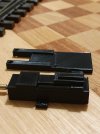
After a bit of learning my way around the excellent TinkerCAD, I was able to come up with this. Not exactly a prototypical design, but it'll do the job!

3mm square stainless captive nuts in the base plate allow it to be bolted to the switch ties and for the actuator cover to be bolted to the top

20201031_204928.jpg

20201101_182251.jpg

20201101_182232.jpg
20201101_182308.jpg

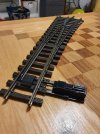
The threaded rod on the end of the actuator goes into a C shaped connector which the switch pushbar is attached to.

The baseplate has a 6mm hole towards the far end to allow the air line to exit through the baseboard and keeps it hidden.

Once it's been proven effective in use I think I will revise the design to suit the SVR actuators. The standard 'screwed to a plate' approach is a bit basic looking and It will keep all the switches looking consistent.
 

Attachments

  • 20201031_204908.jpg
    20201031_204908.jpg
    240 KB · Views: 0
  • 20201031_204848.jpg
    20201031_204848.jpg
    285.8 KB · Views: 1
Last edited:
8 Mar 2014
7,806
972
San Diego
Country
Armenia
www.elmassian.com
Best answers
0
Country flag
you might want to make one that also has the motor parallel to the tracks with a simple bellcrank.

I needed this for switchyards and double tracks where the right angle attachment was too wide.

Greg
 
  • Like
Reactions: 1 user

DGE-Railroad

The Orchard Line
26 Jan 2020
607
89
52
United Kingdom
Best answers
0
Country flag
I think you're absolutely right Greg - I have some dual tracks which, in order to keep the unpressurised switch direction to be the mainline, needs the actuator on the 'inside' where it may start to look a bit tight.

If this tests okay in operation I'll look to do a cranked variant
 
8 Mar 2014
7,806
972
San Diego
Country
Armenia
www.elmassian.com
Best answers
0
Country flag
Ahh, I see you have learned that your want the "unpressurized" state to be default. This helps me when I run a track on DC as my DCC controllers are fed from the track.

Greg
 
  • Like
Reactions: 1 user

DGE-Railroad

The Orchard Line
26 Jan 2020
607
89
52
United Kingdom
Best answers
0
Country flag
Yep, it was as I was putting the switches on the baseboard with the actuators attached at random that I thought, hold on...if control fails, how do I want these to default?

Glad I thought of it then and not once everything was mounted!

Here's a quick video of one under test. I'm using an 8 gallon garden sprayer as the accumulator.

3d Printed actuator holder for LGB switch under test
 
8 Mar 2014
7,806
972
San Diego
Country
Armenia
www.elmassian.com
Best answers
0
Country flag
So you might look at my page for some examples of switch motors, and there is a "parallel" one, but it has a bit of internal friction I don't like, a friend and I are redesigning:


Greg
 
  • Like
Reactions: 1 user

DGE-Railroad

The Orchard Line
26 Jan 2020
607
89
52
United Kingdom
Best answers
0
Country flag
So you might look at my page for some examples of switch motors, and there is a "parallel" one, but it has a bit of internal friction I don't like, a friend and I are redesigning:


Greg
Brilliant. Will do Greg. Thanks for the tip. Thats tonight taken care of!
 

DGE-Railroad

The Orchard Line
26 Jan 2020
607
89
52
United Kingdom
Best answers
0
Country flag
We will be sharing our 3d files when developed.

Greg
Great news Greg. Thanks for letting me know.

I finalised mine today and was thinking to put the files on Thingiverse or somewhere in case they're of any help to anyone.

If you're happy to/ want to host them, it could make sense to have the different designs together?

Darren
 

DGE-Railroad

The Orchard Line
26 Jan 2020
607
89
52
United Kingdom
Best answers
0
Country flag
Thanks Greg.

If anyone wants to use the files, I've made them publically availble on TinkerCAD (just search for Darren Elmslie, pneumatic, gscale or lgb) . If you'd like to ink to them on your air operated switch page as a focus for things air-operated, please feel free to.

There are multiple files based on what's needed - straight or parallel design, SVR or E-Z Air cylinders. The baseplates are dimensioned to suit LGB R5 switches but I'd imagine they'd work with any LGB switch. It'd be quite easy to remix them to suit other switches I expect.
 
Last edited:

DGE-Railroad

The Orchard Line
26 Jan 2020
607
89
52
United Kingdom
Best answers
0
Country flag
Work has been started on the parallel version.

I took a quick look inside the LGB manual and electrical switch units to see if I could adapt them but decided the simplest approach was probably the E-Z Air design.

Fiest iteration which needs a ton of modification including the pivot pin which I think is probably woefully undersized but you never know for sure until you try, right? :D

20201107_084016.jpg

20201107_083958.jpg


I'm trying to see if j can make the parts common and modular but suspect ita going to be simpler just to have a dedicated parallel housing
 

dunnyrail

DOGS, Garden Railways, Steam Trains, Jive Dancing,
Staff member
GSC Moderator
25 Oct 2009
26,171
4,993
75
St.Neots Cambridgeshire UK
Best answers
0
Country flag
Hm interesting way to do it if it works. Not sure how the wear will apply even with a bigger pin. My choice would have been (and is on my line) to use a bell-crank to swop the movement thus a plate for the bellcrank to be mounted perhaps on an 8 ba screw captured into a short length of suitable brass rod for the pivot. You could I imagine also print the bell-crank with suitable non strong flexible medium?
 
  • Like
Reactions: 1 user
8 Mar 2014
7,806
972
San Diego
Country
Armenia
www.elmassian.com
Best answers
0
Country flag
One thing you will probably need to add is to allow grit to drop out of the "groove" that the perpendicular rod goes through, any dirt that gets into the current design will lock it up.

I think the pin size is not too important, clearly a larger diameter pin should reduce wear, but it might just increase friction also. The original design with a metal pin and a metal swash plate belies the wear, I'm not sure the plastic will wear well enough. This is why we are looking at a crank design, lower friction and really the only wear point will be the pivot.

I need the design to incorporate a microswitch to drive the frog and point power, and would like it to be enclosed.

Greg
 
  • Like
Reactions: 1 user

DGE-Railroad

The Orchard Line
26 Jan 2020
607
89
52
United Kingdom
Best answers
0
Country flag
My immediate thought had been to use a bellcrank, then I looked at Greg's page and studied the E-Z Air version too.

I may end up going the bellcrank route if this defeats me. It still certainly feels more 'right' :D
but I liked the simplicity of the pin/plate approach and it saved me coping with the unwanted lateral movement introduced by the bellcrank. I think this would have needed the actuator and turnout pushrods to be split in two, in order to have the end rods move linearly and the bellcrank ends absorbing the angle changes when the bellcrank arms move off-centre. That said, it's probably minimal as the turnout pushbar only has to move something like 7mm from memory, to switch the track.

Once (if) I get the design sorted, I'll get a lid made for it.
Great thinking about the 'drain' slot Greg. I'll add one of those for any detritous that finds its way in. I don't know what the long-term wear will be like on PLA but in reality the switches aren't getting used much so I'm pretty confident it'll hold up well at least in the short to medium term.

Thankfully I'm electronics-free, so that's one less thing for me to worry about! :p
 

DGE-Railroad

The Orchard Line
26 Jan 2020
607
89
52
United Kingdom
Best answers
0
Country flag
Some positive news regarding the parallel design - it seems to work in PLA.
It's taken a number of revisions to dial it in but I'm happy with it.

I've ended up with a separate design which at the moment is dimensioned for the E-Z Air actuators.

I experimented incorporating a PLA pin on the pushplate, but unsurprisingly a 2mm pin wasn't up to the stresses involved. I couldn't face redesigning it all to increase the pin diameter and am just using a brass nut and bolt.

I removed most of the detail on the top in order to gain clearance being so near to the track, so challenged myself to make some 3D chequerplate and chamfered sides :D I don't think the result is particularly great but to get any better would need an FDM printer or better CAD skill than I have.

Here are some pics and a link to some footage of it in operation. All parts are now on TinkerCAD

20201109_122156.jpg
20201109_122136.jpg
Parallel actuator test
 
Last edited:

DGE-Railroad

The Orchard Line
26 Jan 2020
607
89
52
United Kingdom
Best answers
0
Country flag
Just a quick post to say I've added a second throw arm to the throw arm files .

This was because the original arm had the switch arm 'thrown' at rest. I've made e a secondary arm which should allow the switch to be unthrown at rest.

I realised when I looked at my layout that there were one or two instances
 

dunnyrail

DOGS, Garden Railways, Steam Trains, Jive Dancing,
Staff member
GSC Moderator
25 Oct 2009
26,171
4,993
75
St.Neots Cambridgeshire UK
Best answers
0
Country flag
Some positive news regarding the parallel design - it seems to work in PLA.
It's taken a number of revisions to dial it in but I'm happy with it.

I've ended up with a separate design which at the moment is dimensioned for the E-Z Air actuators.

I experimented incorporating a PLA pin on the pushplate, but unsurprisingly a 2mm pin wasn't up to the stresses involved. I couldn't face redesigning it all to increase the pin diameter and am just using a brass nut and bolt.

I removed most of the detail on the top in order to gain clearance being so near to the track, so challenged myself to make some 3D chequerplate and chamfered sides :D I don't think the result is particularly great but to get any better would need an FDM printer or better CAD skill than I have.

Here are some pics and a link to some footage of it in operation. All parts are now on TinkerCAD

View attachment 275993
View attachment 275994
Parallel actuator test
Brilliant I did doubt that it would work but it does. Super job, no more cranks required!
 
  • Like
Reactions: 1 user

Setheroo

Registered
26 Feb 2021
3
0
37
Milwaukie, Oregon
Best answers
0
Hi Darren, Your design looks amazing. I looked on Tinkercad and did not see them up. Will you share your files?