New LGB wont move

ntpntpntp said:
The vertical board is definitely a 55021 decoder that's been mounted with a tie and wired to the pins. it's got the correct pin layout for the usual direct plug-in, and the other components seem to match photos of a 55021. It's got the usual LGB green/brown/white/yellow wires soldered to the far end.
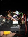
Yeah, the more I look at this, the more I agree with you Nick.

The vertical PCB is an LGB decoder.

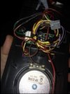
So Jesse, you say the tender PCB is missing? Is this where the P8 card is fitted as this would be next to the speaker I assume....
 
I know this may be stating the obvious, but I am taking it that Jesse is trying to use the loco on DC, rather than DCC.

Depending on where he is, would someone with the necessary kit be able to help, pop over or vice a versa and see if it works.
 
Nodrog1826 said:
I know this may be stating the obvious, but I am taking it that Jesse is trying to use the loco on DC, rather than DCC.

Depending on where he is, would someone with the necessary kit be able to help, pop over or vice a versa and see if it works.
He's in the States mate I believe?

But if someone wants to pay my air fare....
 
The picture shows the main board with a LGB 55021 zip tied to the aluminium heat sink. The decoder is connected to the main board by an LGB55026 Interface cable (which has the heat shrunk push on connectors) and its normal motor and track wires.

The Yellow/White/Brown/Green ribbon cable should go to the motor block? The Black and White cables on the right should go to the smoke unit. Not sure where that brown cable is headed!

You could try bypassing this board and connect the decoder direct to the motor block.....There should be 4 wires (Yellow/White/Brown/Green) connected to the decoder (the board zip tied to the heatsink), these wires should go to pins protruding from the horizontal circuit board. Make a note of which wire goes where. Disconnect them. Note how the ribbon cable connects to the motor block. Disconnect the 4 pins. Connect the 4 wires from the decoder to the motor block in the same colour order that the ribbon cable was connected.

Try it.
 
Thank you all, yes I simply want to run it in DC just to see it go. I am considering my options for DCC for all of my locomotives at the moment. All that is in the tender is the p8 sound card.
 
Jesse,

Is there a bank of (4) switches on that board? If so, disconnect the 4 wires (Green/White/Brown/Yellow) that come from the decoder and that are plugged into the main board - note the position of each wire first! Also disconnect the 6 pin connector from the main board that also connects to the decoder (via the heat shrunk push pins). Change all of the switches over and give it a go. There may be a legend next to the switches - "No Dec" and "Dec" - for analogue op, change them to the "No Dec" position.
 
The P8 is not designed to run on regular DC.
It does not have a battery back up and relies on a constant track voltage (DCC) or on board batteries for power.
For regular DC use you should be using a PB9/PB11.
 
I have heard that the king of LGB lives within 10.miles of me, yet I have never met him. This may.be one for him. Does anyone know a guy named Klaus?
 
Tony, I have an older but great Blue streak transformer. It is clean an filtered DC. It powers my entire 250 foot loop no problem and works great with MTH DCS. I only have it on an 8 ft LGB circle inside for this so I know I have enough power. I also ran another locomotive just to.be sure.
 
Here is the inside of the tender.  The phenix p8, a lot of wires.  There is a grey plug that insist notice before!  Wonder if this is a clue?  Maybe it`s just missing a component and they have it set to where it will not work in DC?  Do any of you know what fits on this plug?  The wires seem to go straight to the board on the bottom of the tender, not the phenix sound.
 

Attachments

  • image.jpg
    image.jpg
    16.1 KB · Views: 56
  • image.jpg
    image.jpg
    15.7 KB · Views: 50
Jesse, if Klaus lives within ten miles of you, you're a lucky man. He is an LGB and electronics expert and will be able to sort it out. Contact him through his website:

http://www.traincraftbyklaus.com/About_Us.html

He has helped me many times over the years with LGB and Massoth and is a great guy.

Keith
 
Maybe that plug is a way to connect electrically, the loco to the tender.

BTW Jesse, you do realise when you get it to work, you are going to have to post a video.
 
muns said:
The picture shows the main board with a LGB 55021 zip tied to the aluminium heat sink. The decoder is connected to the main board by an LGB55026 Interface cable (which has the heat shrunk push on connectors) and its normal motor and track wires.

The Yellow/White/Brown/Green ribbon cable should go to the motor block? The Black and White cables on the right should go to the smoke unit. Not sure where that brown cable is headed!

You could try bypassing this board and connect the decoder direct to the motor block.....There should be 4 wires (Yellow/White/Brown/Green) connected to the decoder (the board zip tied to the heatsink), these wires should go to pins protruding from the horizontal circuit board. Make a note of which wire goes where. Disconnect them. Note how the ribbon cable connects to the motor block. Disconnect the 4 pins. Connect the 4 wires from the decoder to the motor block in the same colour order that the ribbon cable was connected.

Try it.
Fast, and dirty..
Can you not just throw all the DIP switches, and run on analogue. - To prove it works??
 
I wonder if the power connection from the tender has been disconnected, although the loco has its own pick-ups on the Mogul they often don't work very well and most of the power comes from the tender.
 
Another quick suggestion for a relatively easy first test.... pull the four connectors (yellow-white-green-brown) off the pins on the motor block, and tuck them safely out of the way - now simply bridge across each pair of track/motor pins on the motor block by connecting the yellow pin to the white pin, and the green pin to the brown pin (of course the pins themselves are not actually coloured, I'm referring to which pin that coloured wire was connected to) - in other words, connect the left outer and left inner pins together, and the same for the inner and outer right pins. All this does is provide a direct power connection from the wheels to the motor - so now just apply some DC power to the wheels and/or the skates, and see if the motor turns! If it does, then your problem lies in the circuitry somewhere - but at least that eliminates the (small) possibility of a duff motor!

Then you can try Muns' suggestion to test the decoder, and progress from there....

Jon.
 
CV 29 =4 for 14 speed steps and DC.
CV29 =6 for 28/128 steps and DC.
Add 32 for long addressing....36 or 38.
The new Allegra shipped with 28 speed steps and did not run properly on a friends MTS II system as MTS II is 14 steps only!!
 
Back
Top Bottom