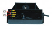
Modifying address of a Massoth 8156601 1-channel switch decoder

railaddict

Registered
Country flag
I bought recently in second hand a couple of above decoders and would like to modify their addresses.

Do I need to do this on the programming track or can I go the POM way?
 
I would always advocate using the programming track.. Especially for an 'unknown' (secondhand, I presume) device..
 
I bought them from a member of another large scale forum in France. I already bought the track cleaning locomotive from him earlier with no problems. I'll follow your advice.
 
I don't think you can POM accessory decoder addresses*. Don't forget you need to attach a point motor to the accessory decoder before you program it in service mode / programming track.
* You can configure Massoth accessory decoders to use loco addresses but that's very unusual. In that case I guess you could use POM.
 
May sound silly, but what does the Massoth manual say?

The manual I found says:

All described programming methods (except PoM) are to be executed on a programming track. Check the manual of your central station or programming module for the correct procedure. Programming will be achieved at all times even if there is no confirmation signal possible.

That is section 3, section 3.1 tells you how to set address with POM.

Doing POM does not imply that the decoder gets a loco address...

I'd say RTFM, the answers are there.

Greg
 
There are two models of the single channel decoder, 8156601 is model II. The manual for that can be found here:
8156601 Switch Decoder 1K II – Massoth Elektronik GmbH in case your second hand purchase did not include manuals.

As you say Greg Section 3.1 of that manual tells you how to set the switch address using "learning mode" which is useful and removes the need for attachment using programming track / service mode This is basically what the OP wanted, so good spot Greg. This will give the device a "switch address" not a "loco address" which is what you would normally want. I assume this will work even if you have programming lock in place (CV15 and CV16 different values) but it doesn't say one way or the other.

This is not quite the same as POM as you can't set any of the other CVs. You can only set any other CVs using POM if the device is assigned a "loco address" (doesn't say this is this manual, but it does in the Massoth 4-Channel switch decoder manual). So in line what what PhilP PhilP said in post #2, I think my advice would be to use programming track / service mode to make sure there were no odd settings you did not want, probably to do a decoder reset so you know you have a "clean slate". After that you could use the "learning mode" to change the switch address if you wanted, but that would probably mean lifting the decoder to temporarily short out the contact pins, which might be more trouble that it is worth.
 
Thanks, Greg and Dave,

I have the manual for the decoders and still that of 8156001 which is for four switches. I had three of those initially but two got destroyed by water, hence the purchase of these single-channel decoders to avoid repeating the problem. I have asked the former owner how he programmed the switches. This was done on the programming track. So I'll go that way to modify the address.
 
In a way, connecting the decoder to the rails in normal DCC mode, and issuing a accessory command is really POM for an accessory decoder.

I use Digitrax DS64's and they have never "seen" service mode/programming track. A lot easier, and I do power all 28 turnout decoders from the rails, just for convenience.

Greg
 
Coming back to this topic.
I want to change the address of some of these decoders. According to the manual, i have to write value 242 in cv 15 in order to unlock the decoder protection. And, if I want to give it address 1 for instance, put value 1 in cv 32 and value 0 in cv 15 to "relock". Changing value of cv 32 does not work, so when I test the switch after programming, it still has its old address.

As the person you bought the unit from had several:
There is no guarantee that CV 16 is set to '242'. - It would be normal for each unit to be given a different 'locking value'.

See section 3.3 of the manual, for setting the CV 15 / 16 values back to the default.
Section 3.4 gives programming examples for a first, and subsequent units..

PhilP.
 
Here I am again. I am programming with the navigator on the programming track, not with the MST. I managed to reset the decoder to factory settings, or what I assume to be, but I still have the problem:cv 15=242, cv16, not. I don't understand the table in the manual (attachment 2). In fact, when I reset the decoder, I went into CV8 and, not knowing which value I should give it, I put 11 and afterwards the address of the decoder had been changed to factory standard:1 and it works. The problem is that I would like to change this address.
 
OK, just sitting to breakfast, so I did not read the manual (please tell me you did read the manual).

I don't think decoder lock is on by default. If I am wrong, someone correct me.

Why don't you do the address programming as I mentioned in post #5?

I think this has become unnecessarily difficult. You did accomplish a full reset, so the simple "learning" mode is the easiest, That is indeed why that mode exists, to not be required to move it to the programming track.

The whole idea is you buy one, put it in place and then do the learning mode programming method. Simple, easy. (In your case, one extra step was to do a full reset, to make it like new, out of the box).

Greg
 
In principle you're right Greg but in practice it would be difficult to put it in learning mode with the decoder in place, because of where the pins are you need to short out, which are very short (hah!) and under the device.
1599499897947.png
I think you would need to do that on the bench.

Given that you have the device in programming mode, having done a successful reset you should just be able to change CV32 to 5 for example and the accessory address should then be 5.

FYI table 2 just lists the CVs that are reset and the values they are reset to. So in your case you used reset value of 11 in CV8 which amongst other things sets the address CV32 to 1 which is what you have found.

HTH
 
I see your point, of course you could just have jumpers to the main line and program it anywhere, as opposed to physically moving it to the programming track, but I get it that you have to do it from underneath.

I still maintain that the POM method is easier since the common theme of this thread seems to be the inability to use service mode (programming track) and getting distracted by the lock mode.

I like it simple.

Greg
 
To reset the programming lock to the default value = write 16 to CV8 - Then use write 242 to CV15 to unlock. If you decide to change the lock value, write it to CV16 and then to CV15 (to unlock), set CV15 to 0 when programming is complete.
 
BTW, POM is only available for this decoder when it is in "Loco address" mode and not "Switch address" mode.
 
I don't think that is correct, can you read the section of the manual I referenced?

My reference is in post #5

The link is in post above, I used this link:
Then I went to the manual linked on that page.

Section 3.1 clearly says you use a "switch command"..... in conjunction with jumpering the pins... I see no other reference or constraint or pre-condition.

I think it is mode-independent.... again simple and designed to be.

Greg
 
I refer to this (page 3 of the manual):

• digital operation (NMRA/DCC)
• operation mode: switch address - 1 function output (SW1) (for motor and EPL-drives) - 1...2047 switch addresses - programming: CV, Register
• operation mode: loco address - 2 function outputs (A1/A2) - 1...10239 loco addresses - Programming: CV, Reg., POM
• 2 separate contact inputs (K1/K2) for manual operation
• programmable functions
• simple function assignment
• Quick Programming function (3.1)
• short circuit and overload protect.
• reset function for all CV values
 
Back
Top Bottom