Micron MR603c P1 P2 outlets

collectors

Registered
Country flag
Hi, Hope you all had a cheap Christmas so you can spend more on your models, lol.
My question is the Micron MR603c P1 P2 receiver outlets a fixed value, or is it dependent on the board input. My input will be around 16v & was wondering on resistor size for the bi-led direction lights.
 
Hi, Hope you all had a cheap Christmas so you can spend more on your models, lol.
My question is the Micron MR603c P1 P2 receiver outlets a fixed value, or is it dependent on the board input. My input will be around 16v & was wondering on resistor size for the bi-led direction lights.
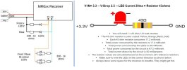
Fixed value..
The P outputs are logic-level outputs from the CPU (well, one of them) so 3.3-3.5V.
You will need to factor in the maximum current you can sink through these outputs, and you may need to play with the resistor values a little, as white and red LEDs, have different forward voltages.

Yell, if you need more help..

PhilP.
 
OK, thanks Phil. Might have to double check the output. Not sure if it can work. But could a 2 leg bi led be made to work. The one that you just revers the polarity. >
Yes:
The P1 & P2 outputs give 3.5V when 'on' and 0V when 'off'.
P1 is on in the forwards direction, and P2 in the reverse direction. - So the polarity of the pair of outputs reverses, with direction.

PhilP
 

Attachments

Yes:
The P1 & P2 outputs give 3.5V when 'on' and 0V when 'off'.
P1 is on in the forwards direction, and P2 in the reverse direction. - So the polarity of the pair of outputs reverses, with direction.

PhilP
Thanks Phil, that's what i'm after. Micron could do with a re-vamp of the web stite. He said to me a long time back he was going to update it to make things clearer.
 
Thanks Phil, that's what i'm after. Micron could do with a re-vamp of the web stite. He said to me a long time back he was going to update it to make things clearer.
I have trouble with it on the Smartie-Phone..
It does not refresh to the latest content, so I have to check on the laptop occasionally.

PhilP
 
It depends a little on the LEDs you are using.. Plus how bright you want them.

An added 'gotcha' is that different colour LEDs have different forward voltages, so you have to compromise on your resistor values.

Also remember that 'we' have to allow for customers not realising that the limits are for the total current that these connections can cope with. - I have people wanting to drive four LEDs, so you really only want 3-4mA through each LED.

Your calculations are for ONE red LED. - Have you done the same for a typical white, or warm-white, LED?

I would base your calculations on around 10-12mA through the LED, which I think you will find more than bright enough.

(I tend to not go much below 150 ohm for series resistors)

PhilP
 
I have a 603 that I used bi-directional (two wire) LEDs in April this year, I used 330 ohm resistors and had problems, and discussed with Phil via email, long story short, I ended up using 660 ohm resistors, as the different rating between the red and white elements caused issues, with only the red LED lighting, nothing from the white LED. I am sure PhilP PhilP may recall this now.
 
It will also depend on which version of the MR603 the OP has. - There were some changes, from version to version..

PhilP
 
It depends a little on the LEDs you are using.. Plus how bright you want them.

An added 'gotcha' is that different colour LEDs have different forward voltages, so you have to compromise on your resistor values.

Also remember that 'we' have to allow for customers not realising that the limits are for the total current that these connections can cope with. - I have people wanting to drive four LEDs, so you really only want 3-4mA through each LED.

Your calculations are for ONE red LED. - Have you done the same for a typical white, or warm-white, LED?

I would base your calculations on around 10-12mA through the LED, which I think you will find more than bright enough.

(I tend to not go much below 150 ohm for series resistors)

PhilP
Phil,
I hope you don't mind jumping in on this thread but it seems you might be able to assist me with a similar question. I confess not being as informed about LED's etc as much as I should be - despite trying to decipher the many articles Google has thrown at me ...

I am about to install the MR603c receiver and want to connect a 3mm white diffused LED to P1.

My understanding from the Micron doco is that pads P1 and P2 for the LEDs are limited to a load of 20mA each.

If I understand correctly, a resister is required on each LED such that the current is limited to (less than) 20mA across the LED so as not to destroy the board?

If that is correct I should aim for, as you suggested, a target Forward Current of 10-12mA when calculating the resistance value ?

We also know from Micron that P1 and P2 are each supplying a fixed 3.3V when they are 'on' and I read that a typical Forward Voltage for a 3mm diffused white LED is 3.0V

So, from what I can gather I should use 3.0 volts as the Forward Voltage for the LED, say 10mA for the Forward Current and 3.3V for the Supply Voltage when calculating the resistor value ??

Or have I totally missed something here ?

Thanks.
Correct!

But to save going to the online calculator, I would suggest 150 Ohms.

PhilP
 
Correct!

But to save going to the online calculator, I would suggest 150 Ohms.

PhilP
Wow ok, looks like I did learn something today after all !

Thanks Phil.


Just curious..calculator suggests 30 ohms based on those values, so using 150ohms is just 'best practice' or simply more insurance that you won't munt the receiver???
 
Yes, a 'belt and braces' value..
Hi output LEDs only need 3-4mA
Certainly,on steam outline models, a 'dimmer' warm-white LED looks better. - IMHO.

You can tweak the values a little if you want more light output, but the very nature of the way a LED works, it is not so easy to dim the output.

You might find this useful:


PhilP
Yeah magic, its just going to be an extension of the status LED on the board. So it might end up just going in the cab (its a diesel loco)…. Unless i can fashion a wee lamp to hold it to go onto the headstock… we’ll see.

Will check out the website… thanks… am used to working with 22kV so all this micro stuff is a bit foreign to me at the moment
Appreciate the help.

Cheers
 
Plenty of learning to do with Deltang, very clever and does so many things but updating options takes some reading, learning and getting used to.
 
Yes, a 'belt and braces' value..
Hi output LEDs only need 3-4mA
Certainly,on steam outline models, a 'dimmer' warm-white LED looks better. - IMHO.

You can tweak the values a little if you want more light output, but the very nature of the way a LED works, it is not so easy to dim the output.

You might find this useful:


PhilP
One last question (for today :sunglasses: ), the Micron MR603 doco suggests there is a 120Ohm resister already on the PCB... "P1 to P4 have a series 120 ohm resistor on the PCB," So do we need to take that into consideration when selecting the resister we'll add to the LED on P1 ?

Cheers Phil.
 
One last question (for today :sunglasses: ), the Micron MR603 doco suggests there is a 120Ohm resister already on the PCB... "P1 to P4 have a series 120 ohm resistor on the PCB," So do we need to take that into consideration when selecting the resister we'll add to the LED on P1 ?

Cheers Phil.
That basically means that we have thought about it, and that you *probably* won't destroy the chip if you forget to add an additional resistor..
BUT
Only if you are using the 3.3V of the output to ground.

A little like fitting a diode in series with the positive supply, to protect the receiver from being connected reverse polarity.

PhilP
 
So, what I hear is for the sake of a 50c resistor, get into the habit of adding the 150 ohm resister as well :sunglasses:

...i like that idea - i cant afford to keep replacing chips !!
 
Last edited:
Back
Top Bottom