Massoth Automatic Control for Colour Light Signals

supagav

USA standard gauge in the late 1960's, in 1:29th.
Hi,

I just wanted to ask if anyone could help me with any suggestions or advice please?

I would like to use some colour light signals on a portion of our line and drive these using the Massoth Feedback module (with wireless RC upgrade) and the associated train detection module. I already have one of these setups in place driving LGB semaphore signals and I am very happy with the results. After a bit of initial tweaking, the system works great every time and has proven very reliable.

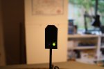
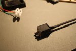
I wish to replicate the same setup with another set of Massoth wireless feedback and train detection modules in another area, but this time to drive a pair of LED colour light signals. I was considering some US style signals from Shiloh, which operate up to 24V AC or DC, with a wire for each aspect and a common ground (positive +).

http://www.shilohsignals.com/index.php/g-signals/

The problem I have is that I am not sure of what kind of accessory decoder I should use to operate these kind of signals? Can I use a Massoth switch decoder to drive these? Or maybe something from another manufacturer? I need to get something which can take an accessory command and drive the LED signals, with either red or green aspects. Maybe even some kind of small relay board?

Any help or ideas would be gratefully appreciated!

Many thanks,
Gavin
 
PS: just another quick thought. We are currently running three Navigator handsets and one wireless feedback module, making 4 wireless units so far. I think I read that there was a limit to the number that can be used at one time? Does anyone have any experience with this?

Thanks, G
 
supagav said:
PS: just another quick thought. We are currently running three Navigator handsets and one wireless feedback module, making 4 wireless units so far. I think I read that there was a limit to the number that can be used at one time? Does anyone have any experience with this?

Thanks, G
As far as I can understand reading the Massoth documentation:

- One wireless receiver can receive information from 8 wireless units
- Two wireless receivers can be used increasing the total number of wireless units to 16

Not sure how the wireless feedback module works, but the tethered one can have 4 slaves attached to the master module and only the master uses an ID. If this is the same for wireless you can have 5 feedback modules utilizing only 1 wireless ID.
 
Hello Gavin,

I've never done it, but according to the manual you can control lights with a wire for each aspect and a common with the Massoth switch decoder.

You might also want to consider specialist signal light decoders such as the Littfinski LS-DEC-xx or the Train-Tech SC1,SC2 or SC3. Probably there are others.
 
Qdecoder is another supplier of light decoders. They have versions with the option to have separate feed for track (which carry the digital signal) and power. This will eliminate the effect of light flickering when switches are thrown. If you don't have a separate power supply for the lights, you can still use the track supply for both the digital signal and the lights. The Qdecoders use switch adresses.
 
tryed 8,on one reciver.. no joy, best i got was 4.wireless navs per reciver :o
 
Thanks for the replies guys, much appreciated.

I will check those signal decoders out too.

As for the limit of wireless Navigators, the documentation for the newer version of the RC Receiver says that up to 4 units can be used, yet the information on the Massoth website says the limit is 8 handsets. Clear as mud!
 
Just another quick update...

I was thinking of maybe setting up a small bench test with some bi coloured LEDs as I have a spare Massoth switch decoder in a drawer. That way I could have a little play about with things before I actually purchase any signals.

Does anyone know what CVs I should be looking at to achieve this? I see there is one for continuous output? I would like to use one pair of outputs on the decoder to switch between each aspect, and a positive common (+).

Also what would the decoder be outputting? AC (DCC) track voltage? (I will be using resistors to step it down accordingly).

I'm sorry that these are quite basic questions but I was just wondering if anyone has done this before as it could save me a bit of time tinkering and working it out myself.

Thanks again,
G
 
I have adapted Playmobil signals and a Bachmann gantry to run off the DCC track voltage, by fitting bias resistors.

The switching of the lights though, is done by LGB Type 2 accessory switches attached to the LGB point motors.

Having looked at the Shiloh website, I reckon you could do the same with their signals (you wouldn't need the biasing resistors though as they are 24V DC or AC)....
 
Another thought Gav!

As you are using these modules to operate LGB semaphore signals, have you considered LGB colour light signals?

These operate mechanically by moving a red or green spectacle in front of a filament lamp, rather than by switching LEDs....
 
Thanks Gizzy!

It is a good thought and one which I had mulled over, but the signals I'm thinking about are very accurate for the US railways we model. That was the thinking behind my preference to try to go down that route. The LGB US style semaphores we use now are great, they work well and are really reliable, I mean this as no bad criticism but they are just a generic representation and aren't as close as some of the other signals on the market.
 
I was wondering if you could use a Massoth Switch Decoder to drive these signals?

I believe you can adjust the outputs from a pulse for point motor control to either a permanent on or off state.

Might be worth a PM to Muns, of GRO to confirm this?

Or contact him via his website here....

http://www.gardenrailoutlet.co.uk/contactus
 
Thanks Gizzy,

That was what I was thinking... I know that there are definitely more elegant signal control decoders out there, but I thought to use what we already have if possible. WE have some spare channels on a couple of Massoth switch decoders out on our line where I plan to install the signals, so it makes sense to explore that route first.

If I can set it up as a continuous output, switching between the two separate negative (-) leads of the LEDs, I figure it could control a simple two aspect colour light signal which would be more than adequate for our needs.
 
This is possible with a Massoth Switch Decoder......

Set both outputs (F1/F2) to Continuous output - CV51 & 52 to 0.

Connect between F1 & +, F2 & +

If you switch the output one way, one light will illuminate, switch it the other way and the other will illuminate.
 
Thank you very much for that Mark, that was exactly what I was looking for! Many thanks for your help :)

I will have a play around with it on our work bench next week.
 
FYI I tried this with a single channel Massoth decoder, and it works fine if you change CV 51 and 52 to 0 as described above. It is a little strange as there are only 2 output wires from the decoder, but the polarities change so if you wire a couple of LEDs to the outputs, one reverse polarity to the other, you get the effect. Include a resistor inline as well as by default you get the full track voltage; you can change this with CV 71 (default 15 = full voltage). I set CV 71 to 2 and it outputs about 3v which is fine for the LEDs I was using. The advantage of this is it is basically "wireless" in that you can run it from the track power, so if you have a solitary remote colour signal it is very convenient. Only two aspects though. If you want multi-aspect or have multiple signals in a cluster then the LDT LS-DEC decoder as mentioned by Cliff is good; again you can drive it just from the track so no additional wires back to base are required, but it is not weather proof unlike the Massoth single channel decoder so you would have to make it removeable. You can also get variations of the LS-DEC for British, German and other country railway signals.
 
I thought I would give this a try so I built a prototype Hp0/Hp1 colour signal from 1mm plasticard and a couple of 5mm LEDs.
2980-310815145219.jpeg

I used a plug-in connector to make the signal easily removable. It works fine on two wires, driven from an LDT LS-DEC light signal decoder.
2980-310815145652.jpeg

With a Lenz handset you switch the light by using + and - for the accessory address to switch between red and green. The only problem with my prototype is that I used a drinking straw for the mast which is not quite strong enough.


Attachments

  • IMG_0152.JPG
    IMG_0152.JPG
    141.4 KB · Views: 7
  • IMG_0155.JPG
    IMG_0155.JPG
    196.6 KB · Views: 6
Back
Top Bottom