LGB Stainz loco motor block to circuit board connection

The mechanic

Registered
24 Nov 2016
181
15
61
South Staffordshire UK and Co. Wexford Eire
Best answers
0
Country flag
Hello everyone, I know someone here can answer this one....

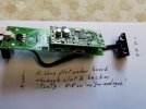
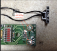
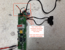
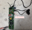
I am attempting to reconnect the 4-wire motor block connector to a replacement circuit board(photos below). The issue that I am having is that all four wires are black, the connector does not have any wiring colour codes (but strangely the motor block does!) and the circuit board just says "motor" (and stubbornly laughs at me!). As I do not want the "magic smoke" to appear, I thought it prudent to ask!

Coming from an auto-electrical background, I find it frustrating that there is no real colour coding or notation on the board to make replacement of components a little easier

Thanks in advance

Dave
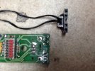
image.jpeg
 

Paul2727

Registered
5 Jun 2018
655
85
The Cotswolds
Best answers
0
Country flag
There have been so many variations of the stainz it would help if you know the model number.
Regards,
Paul.
 

The mechanic

Registered
24 Nov 2016
181
15
61
South Staffordshire UK and Co. Wexford Eire
Best answers
0
Country flag
Trust no one ha ha! Get a meter and verify for yourself would be my advice.

Greg

How would you propose I use the meter and for what purpose?

All wires are black, I know the position on the motor block connector, the only problem is that there are no corresponding markings on the circuit board to indicate which position on the block connector is linked to which solder tag on the circuit board and that basically is all I need to know!

Thanks

Dave
 

The mechanic

Registered
24 Nov 2016
181
15
61
South Staffordshire UK and Co. Wexford Eire
Best answers
0
Country flag
There have been so many variations of the stainz it would help if you know the model number.
Regards,
Paul.
Hi Paul,

The board is a spare from a Stainz, but I don't intend using it for a Stainz, just to drive an LGB motor block, allow manual "on-off" switching and facilitate connection of a lighting circuit on a renovated Corpet Louvet that I have resurrected from a bag of bits. Therefore I don't have a model number to go off, just a circuit board.
 
8 Mar 2014
7,806
972
San Diego
Country
Armenia
www.elmassian.com
Best answers
0
Country flag
So, you said you come from an auto-electrical background, which would be normally 12v dc... same stuff... you did not use an ohmmeter or voltmeter?

So I would use the ohms settings to determine the 4 female connectors on the plug, most likely motor+ motor-, right hand rail, left hand rail.

Then, a little trickier, determine what the pins on the board are. Assuming analog, 2 of the pins would lead to a general part that would have rectifiers to lights, etc. 2 other pins would come from the switch block, for the motor.

My guess is the problem is that the connector can go on either way. I'll bet the outer 2 pins are either motor or track pickups, and the inner 2 pins are the other, i.e. if you put the plug on backwards, the worst that happens is the loco runs backwards.

Greg
 

phils2um

Phil S
11 Sep 2015
1,522
423
Ann Arbor, Michigan
Country
United-States
Best answers
0
Country flag
As far as I'm aware all LGB and MLGB four pin motor blocks have the two outer pins marked gr and ge (grün und gelb or, in english green and yellow) and they connect to the motor. The two inner pins marked bn and ws (braun und weiss, brown and white) go to the rails through bus bars in the motor block that contact the wheel brushes and skates.

Yellow = Mot +
Green = Mot -
Brown = L track rail (looking from behind toward the forward direction of travel)
White = R track rail

But the above does not really help answer your problem. I'd carefully look at the interface board again to see if there are gr, ge, bn, ws labels on it. The photo you attached is not clear enough to tell. I can see two tall pins on the circuit board, are there another two and are they labelled? I think these are for a 4 lead decoder harness, Mot +/- and track L/R. When the red switches are set for decoder operation there should be continuity between each pin and the corresponding solder pad to which you want to attach the motor block leads. Try with the red switches all one direction then again in the other. The direction of these switches determine whether the board is set for analog only or MZS (DCC). Note that this is only an interface board. A decoder is still needed for DCC operation.

Note also that when the switches are set for analog only there will be continuity between one of the motor connections and one track connection on the interface board. The other track and motor connections may or may not show continuity. Some of these interface boards have intervening electronics to delay motor operation so that lights come on first. When set for DCC there should not be cross-continuity between any of the ge, gr, bn, ws connections on the interface board.

On the motor block you will see the motor winding resistance between the ge and gr, the mot + and mot - pins.

Edit: added cross-continuity to further clarify above.
 
Last edited:

dunnyrail

DOGS, Garden Railways, Steam Trains, Jive Dancing,
Staff member
GSC Moderator
25 Oct 2009
26,171
4,993
75
St.Neots Cambridgeshire UK
Best answers
0
Country flag
I was pretty sure that was the case as Phil said so the plug is Motor/track/track/motor thus it does not matter that much which way you shove the plug in. The only issue would be that if it was reversed the Loco would go the wrong way to that expected. There is an expectation that a chipped loco will go Chimney First as forwards. Thus if it goes bunker first for forwards (on the controller) you have shoved it in the wrong way round.
 

The mechanic

Registered
24 Nov 2016
181
15
61
South Staffordshire UK and Co. Wexford Eire
Best answers
0
Country flag
As far as I'm aware all LGB and MLGB four pin motor blocks have the two outer pins marked gr and ge (grün und gelb or, in english green and yellow) and they connect to the motor. The two inner pins marked bn and ws (braun und weiss, brown and white) go to the rails through bus bars in the motor block that contact the wheel brushes and skates.

Yellow = Mot +
Green = Mot -
Brown = L track rail (looking from behind toward the forward direction of travel)
White = R track rail

But the above does not really help answer your problem. I'd carefully look at the interface board again to see if there are gr, ge, bn, ws labels on it. The photo you attached is not clear enough to tell. I can see two tall pins on the circuit board, are there another two and are they labelled? I think these are for a 4 lead decoder harness, Mot +/- and track L/R. When the red switches are set for decoder operation there should be continuity between each pin and the corresponding solder pad to which you want to attach the motor block leads. Try with the red switches all one direction then again in the other. The direction of these switches determine whether the board is set for analog only or MZS (DCC). Note that this is only an interface board. A decoder is still needed for DCC operation.

Note also that when the switches are set for analog only there will be continuity between one of the motor connections and one track connection on the interface board. The other track and motor connections may or may not show continuity. Some of these interface boards have intervening electronics to delay motor operation so that lights come on first. When set for DCC there should not be cross-continuity between any of the ge, gr, bn, ws connections on the interface board.

On the motor block you will see the motor winding resistance between the ge and gr, the mot + and mot - pins.

Edit: added cross-continuity to further clarify above.
Thanks for this Phil,

Yeah, I am using the interface board on DC (analogue) only on a resurrected Corpet that I have rebuilt from a bag of bits so that I can manually isolate and have full lighting. I could not find a dedicated board for a Corpet and this seemed to fit the bill for what I need. Problem is that the previous owner had snipped the four trailing leads from the plug to the board!

I had already determined the connection details at the plug end and totally agree with your instruction.
The big issue, and where it potentially comes crashing down, is where on the board each black wire is connected? There are no labels on the circuit board and as far as I know, no available circuit diagramme to aid connection. Must admit, it feels a bit like bomb-disposal here .... Which wire goes where? ⚡

Just one last observation, the replacement plug that I have has an anti-rotation pip mounded onto it which prevents the plug being fitted 180 degrees opposed.

I'll have another go later and see how I get on

Dave
 
Last edited:

PhilP

G Scale, 7/8th's, Electronics
5 Jun 2013
33,567
3,521
Nottingham
Best answers
0
Country flag
This is from a digital model, so no DIP switch on the circuit board:

Stainz motor+track wiring - web.jpg
NOTE: Block connector is shown from the TOP..

PhilP.
 

PhilP

G Scale, 7/8th's, Electronics
5 Jun 2013
33,567
3,521
Nottingham
Best answers
0
Country flag
Continuity test will 'bleep' 1-4 as you work down, if you have it correct..

PhilP.
 

The mechanic

Registered
24 Nov 2016
181
15
61
South Staffordshire UK and Co. Wexford Eire
Best answers
0
Country flag
This is from a digital model, so no DIP switch on the circuit board:

View attachment 277414
NOTE: Block connector is shown from the TOP..

PhilP.

Ah!..... Now this is more like it!

Thanks a million Phil. As I say, I'll try this later and let you know how I get on

Really appreciate this

Dave
 

The mechanic

Registered
24 Nov 2016
181
15
61
South Staffordshire UK and Co. Wexford Eire
Best answers
0
Country flag
So, you said you come from an auto-electrical background, which would be normally 12v dc... same stuff... you did not use an ohmmeter or voltmeter?

So I would use the ohms settings to determine the 4 female connectors on the plug, most likely motor+ motor-, right hand rail, left hand rail.

Then, a little trickier, determine what the pins on the board are. Assuming analog, 2 of the pins would lead to a general part that would have rectifiers to lights, etc. 2 other pins would come from the switch block, for the motor.

My guess is the problem is that the connector can go on either way. I'll bet the outer 2 pins are either motor or track pickups, and the inner 2 pins are the other, i.e. if you put the plug on backwards, the worst that happens is the loco runs backwards.

Greg

Thanks Greg,

Unfortunately we don't use AVO's in the automotive industry - just stick a nail in the fusebox, turn everything on and look for the smoke!

No seriously, thanks for the input. I'm going to have a serious session with it later now that I know what is supposed to go where and will have my meter on the "horseshoe" setting (ohms)

Fingers crossed!

Dave
 
8 Mar 2014
7,806
972
San Diego
Country
Armenia
www.elmassian.com
Best answers
0
Country flag
This is the picture you first posted:
403646_image.jpeg


This red bits are the "dip switches".... DIP = Dual Inline Pins.... you can see the two rows of pins on your last picture.

Is this not the other side of the board you have?

Greg
 

The mechanic

Registered
24 Nov 2016
181
15
61
South Staffordshire UK and Co. Wexford Eire
Best answers
0
Country flag
Don't really understand your comments Greg. Yes it is my (analogue model) interface board and yes, those are red dip switches. I have only posted one photo of my board on here! The other photos on this thread are not my board. They are of a more up-to-date (digital) interface board (as noted in the text) that have been posted by members in an effort to illustrate how to connect the four black wires and of which I am very thankful.

Greg, I know you mean well mate, but you really confused the hell out of me for a moment there!


Dave

cid%3AA91FA94E-9235-4DC2-95FA-53D754888D9B


Sent from my iPad
This is the picture you first posted:
403646_image.jpeg


This red bits are the "dip switches".... DIP = Dual Inline Pins.... you can see the two rows of pins on your last picture.

Is this not the other side of the board you have?

Greg
 

phils2um

Phil S
11 Sep 2015
1,522
423
Ann Arbor, Michigan
Country
United-States
Best answers
0
Country flag
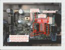
Here are the pins on your interface board that I asked about.
Screen Shot 2020-12-14 at 3.00.03 PM.png

Here is a similar era interface board showing what I tried to explain in my earlier post. This interface board is from my Re 4/4 III but the concept still applies.
Set the board for DCC before checking continuity.
Scan.jpeg
 
Last edited:

The mechanic

Registered
24 Nov 2016
181
15
61
South Staffordshire UK and Co. Wexford Eire
Best answers
0
Country flag
Hi Phil,
Just thought you may like to know, I followed the instructions in your post to the letter. I identified continuity on the two motor leads from the outer connector pins and soldered up. I have continuity on both motor poles all the way from the motor to the two motor decoder connector pins on the board. So far so good.
I then checked continuity from wheel pickups all the way to the pickup decoder connector pins on the interface board, looking good?

So I then tried to connect the cab selector switch to the interface board and apply power to the wheels. Hmm, not so good few sparks at wheels with 12v applied.
Checked 12v from wheels on both poles through board, past big diodes, etc. But no voltage to motor.

Could not get power to motor or lights no matter how DIP switches or selector switch is set.

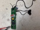
Open to suggestions? Attaching a better picture of board if it helpsimage.jpeg


Dave
 
Last edited:

phils2um

Phil S
11 Sep 2015
1,522
423
Ann Arbor, Michigan
Country
United-States
Best answers
0
Country flag
Hi Dave - Not sure where you've connected the wires from pic. Sounds like you soldered the connector to the decoder harness pins. That is wrong. It needs to be soldered to the motor block wires in the your pic. Only use the decoder harness pins to identify which of the four black wires are gn, ge, br, ws. Hope you didn't smoke something!

Screen Shot 2020-12-14 at 9.41.04 PM.png

Edit added: See my next post!
 
Last edited:

phils2um

Phil S
11 Sep 2015
1,522
423
Ann Arbor, Michigan
Country
United-States
Best answers
0
Country flag
Hi again Dave,

Ignore the comments I wrote on your picture in post 18. I realized the wires I pointed to are the ends of the wires from your motor block connector not yet soldered. These motor block connector wires need to be soldered to the "motor" pads circled below. Use the pic by Phil P. in post 10 as additional guidance. It shows the order in which the connector wires should be soldered to the four "motor" solder pads.
Screen Shot 2020-12-14 at 10.55.41 PM.png

You can check for correctness by doing the following: Connect the off, lights, or lights and motor control switch to the board and set it to the lights and motor position. Plug the motor block connector onto the motor block. Set the interface board for DCC.

Your VOM should now measure no resistance between the ws pin on the motor block and the ws decoder harness pin on the interface board. You should have no resistance between the br pin on the motor block and the br decoder harness pin on the interface board. You should have no resistance between the gr pin on the motor block and the gr decoder harness pin on the interface board. And finally, you should have no resistance between the ge pin on the motor block and the ge decoder harness pin on the interface board.

Next, there should be an open, or high resistance between the br pin and the other three, ws, gr, and ge pins whether measured at the motor block or the decoder harness pins on the interface board. Likewise, there should be an open or high resistance between the ws pin and the other three br, gr, and ge pins.

Finally, you should see motor winding resistance between the gr, and ge pins whether measured at the motor block or the decoder harness pins on the interface board.

Reset the interface board for analog. It should now work with your analog controller.

As an aside, I realize from Phil P.'s pic in post 10 the two pins I've got circled are for connecting the lights, not the decoder harness. I should have looked more carefully.
 
Last edited:

Paul M

Registered
25 Oct 2016
11,881
1,696
60
Royston
Best answers
0
Country flag
Unfortunately we don't use AVO's in the automotive industry - just stick a nail in the fusebox, turn everything on and look for the smoke!
Have you tried for a job with your local electricity supply network?
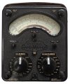
The original AVOs were great, can you still get them?AVO8.jpg