grizzmo
NW Tas
Hi all.
I am converting an old (30+years) analogue geii 4/4 to battery R/C.
I have done the install using a micron MR603c receiver, I removed the skates and brushes and tested as is, it runs fine.
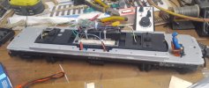
My question is am I missing something in the tests below ?
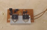
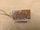
This board was connected to the weight in the chassis (motor board for want of a better name) had 3 wires in each side from each motor and pickups, joining to common busbars, white cable rail pick up and motor, brown cable other rail pick up only and green cable motor only.
The diodes and resisters are in the green motor cable circuit.
brown, white and green leave in a 3 pin plug to the body in smaller gauge wires.
supplying 13v dc to brown and white input powers up the directional lights and raises one panto and drops the other. Reversing polarity swaps it over, needs 9v to start, but isn't really happy sitting at 9-11v on changing over. Above 11v it swaps over nicely.
The above board seems to be only for motor control and as a junction for power pick up?
Tracing out the circuit and measuring the voltage, track voltage is fed to the loco body from the plug on the brown and white cables from this board.
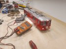
I removed the motor board and put 13v dc directly to the brown and white cables and everything functions the same.
Only difference I see is current draw is lower without the motor board in the circuit.
feeding the motor board, panto's operating was 0.7 amps for 3-4 seconds then 0.2 amps continuous draw for the lights.
feeding joining cable directly, panto's operating was 0.5 amps for 3-4 seconds then 0.15 amps continuous draw for the lights
Is it ok to assume the lower current draw is due to the components on the motor board using some power ?
I think the green wire between boards is a feed from panto if you want to collect power from them.
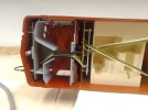
I think this board has the switch track power ,off, panto power and is for dropping track voltage, I think these are 5v incandescent lights ?, directional light control and feeds the panto boards.
I can't see a problem with connecting the brown and white cables to the above board in parallel with the motor output cables on a micron MR603c 3A r/c board. Green wire not needed.
I might have to switch them around if lights and panto's operate the wrong way round, there is a 50 % chance of getting it right
The current draw should be below 3A max rating, as I have read the current draw on these loco motors is below 2A.
I can join the ammeter in the circuit and run it with the loco to be sure if it is really needed.
To me it would function as it did as a track powered loco.
Can anyone see a problem with doing this, am I missing anything?
I am converting an old (30+years) analogue geii 4/4 to battery R/C.
I have done the install using a micron MR603c receiver, I removed the skates and brushes and tested as is, it runs fine.

My question is am I missing something in the tests below ?


This board was connected to the weight in the chassis (motor board for want of a better name) had 3 wires in each side from each motor and pickups, joining to common busbars, white cable rail pick up and motor, brown cable other rail pick up only and green cable motor only.
The diodes and resisters are in the green motor cable circuit.
brown, white and green leave in a 3 pin plug to the body in smaller gauge wires.
supplying 13v dc to brown and white input powers up the directional lights and raises one panto and drops the other. Reversing polarity swaps it over, needs 9v to start, but isn't really happy sitting at 9-11v on changing over. Above 11v it swaps over nicely.
The above board seems to be only for motor control and as a junction for power pick up?
Tracing out the circuit and measuring the voltage, track voltage is fed to the loco body from the plug on the brown and white cables from this board.

I removed the motor board and put 13v dc directly to the brown and white cables and everything functions the same.
Only difference I see is current draw is lower without the motor board in the circuit.
feeding the motor board, panto's operating was 0.7 amps for 3-4 seconds then 0.2 amps continuous draw for the lights.
feeding joining cable directly, panto's operating was 0.5 amps for 3-4 seconds then 0.15 amps continuous draw for the lights
Is it ok to assume the lower current draw is due to the components on the motor board using some power ?
I think the green wire between boards is a feed from panto if you want to collect power from them.

I think this board has the switch track power ,off, panto power and is for dropping track voltage, I think these are 5v incandescent lights ?, directional light control and feeds the panto boards.
I can't see a problem with connecting the brown and white cables to the above board in parallel with the motor output cables on a micron MR603c 3A r/c board. Green wire not needed.
I might have to switch them around if lights and panto's operate the wrong way round, there is a 50 % chance of getting it right
The current draw should be below 3A max rating, as I have read the current draw on these loco motors is below 2A.
I can join the ammeter in the circuit and run it with the loco to be sure if it is really needed.
To me it would function as it did as a track powered loco.
Can anyone see a problem with doing this, am I missing anything?
Last edited:

