Lgb analogue board issues

scook

Registered
24 Oct 2009
283
15
leicester, 3cag
Best answers
0
Country flag
Hi all

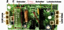
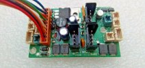
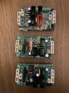
i have an lgb Frank s that I did digitise, and I want to fit an analogue board instead for various reasons . The 2nd motor in the tender needs replacing so I have removed it. The front motor works fine on the decoder, pictured 1st in the boards below. However when I replace the decoder with one of the two analog boards I get nothing, i have connected and unconnected the wires to the tender whilst testing on analogue and I have also used two of the switches to make sure they are not the issue.
would be interested in any suggestions or ideas,

thanks Sam
ED371F3D-4089-4C39-BD5B-2D057CF0D72D.jpeg
 

Eeyore.Boater

Registered
24 Oct 2009
135
18
Stafford
Country
United-Kingdom
Best answers
0
Country flag
I have experienced issues with the M1 and M2 sockets on the analogue board of another LGB twin motor loco. The middle two pins are from the pickups and are cross connected by tracks on the double sided circuit board. The top track under the sockets can sometimes be troublesome and is best dealt with using a small jumper wire. Or maybe its something else.....
 

Brixham

No buffers were hurt at this sign
27 Aug 2010
1,495
120
Best answers
0
Country flag
Shouldn't there be a dummy plug in the decoder socket?
ATM it's ready for a decoder to be plugged in...without a decoder...or a dummy plug...zilch!
 

Software Tools

Registered
18 Jan 2013
311
56
Sydney, Australia
Best answers
0
Country flag
Shouldn't there be a dummy plug in the decoder socket?

Indeed, the bypass PCB "plug" missing on the 10 pin DCC connector for those analog circuit boards. See the red circled part on the image below....

IMG_6780.jpeg
 

Brixham

No buffers were hurt at this sign
27 Aug 2010
1,495
120
Best answers
0
Country flag
I must have a dummy plug somewhere.....but where....
Today I was looking for some Massoth M decoders....which I bought about 6 months ago...Can I find them? nope

I've been looking on the web for the connection diagram of this board...again, nothing

You could link pins A B and C D in the unused 4 way socket that would come from a dual motored loco. This may get the loco working, but without directional headlights. It may also do damage to the circuit board. Linking these pins connects the track feed to a motor terminal.

M
 

Brixham

No buffers were hurt at this sign
27 Aug 2010
1,495
120
Best answers
0
Country flag
Why it's called a 10 pin plug, when it has 13 beats me!!

M
 

Software Tools

Registered
18 Jan 2013
311
56
Sydney, Australia
Best answers
0
Country flag
Why it's called a 10 pin plug, when it has 13 beats me!!

10 of the pins go to a decoder.... so the decoder plug has 10 sockets and 10 wires. The 3 pins in the second row are just for bypass use.

IMG_6782.jpeg
 

Dan

Registered
28 Jan 2010
661
52
Eastern MA, USA
Best answers
0
Country flag
The first board with the red socket is the DCC version and the red socket is the SUSI bus for the LGB sound board. The other 2 boards are DC only and the jumper board is needed for it to work or attach the DCC add on board. These are the boards from the original LGB during the early 2000's and are no longer made by Marklin and they came from Massoth.