LGB 4 Wheel Railbus Batteryfication T25 (2065?) Battery Conversion

dunnyrail

DOGS, Garden Railways, Steam Trains, Jive Dancing,
Staff member
GSC Moderator
Country flag
So the latest project in my quest for a complete Battey World of Power. In truth the little LGB Railbuses are one of the best runners on Track Power due to their ability to keep all 4 Wheels on tha Track. But as I am going all Battery and had this in stock plus having a few others already up and running in DCC well battery it was.

Here is the donor Railcar. It is a very old one, quite likely originaly from a 2 car set and has had some dodgy reworking in the past which included soldered Wires from the Lower Circuit Board to the motor and many other bodgy electrics to it. Just as well it was being fixed!
image.jpeg
A quick test showed that the motor ran ok so no wories in that department other than a major clean up,of the excess oil on wheels, slidy bogie area's and gear boxes. Some people really do like to splash the wrong type of oil everywhere!

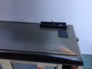
For those that have never pulled one of these to bits there is a bit of an order as in all things LGB. First to get the roof off a good push underneath through the door removes it leaving a circuit board in place which sits on the 4 wires that provide power from the lower circuit board through the 4 metal handrails to the top circuit board. Clever atuff LGB. Turning the beast over reveals the lower picture view.

To remove the cover over the motor the 4 Yellow Marked screws are removed. This reveals the motor that can be unplugged form the circuit board. Remember how it goes back, take a picture! The red marked screws remove the sideframe assembly and the green marked ones allow the ends with sub rood to be removed.
image.jpeg
Here you can see the underbely after the Yellow Screws and cover have been removed. Below is another (Piggy Nosed ine) that has been chipped with a Dentz Chip showing where it is possible to mount things.
image.jpeg

Below you can see Test Fitting Battery and all the other kit to make this work, all to be mounted under the roof. At this stage the poles to the roof board have not yet been clipped short. They have been to allow all this kit to sit without those poles trashing it all!image.jpeg
I have used a Fosworks Receiver (Rx-2H), Transmitter (Tx-2.1), Wiring Loom, Battery Pack (NiMh 3 long by 4 wide), Cobra ESC-165 Speed Controller and a My Loco Sound Diesel Sound Unit with a small speaker. All seen above before fully and safely mounting below the roof.
 
Last edited:
Wrapping up this little conversion are a few more pics. Below out in the line prior to completion but testing all the functions. As ever a little tweeking of the Souncard was required by use of the Peter Spoerer Remote Control to adjust some settings. What I had never realised about these before is that Sound Level is adjusted when something is working. Thus on Tickover which was near silent - (mine is the wrong way round) upped the volume nicely. This appears to also apply with the Bell and Horn which are the only things that interest me. The third button Starts and Stops the Motor.

You can see in this picture where I have placed the On/Off Button, charging socket and where the screw that holds the Fuse in place protrudes through the roof line. Plus the surplus holes at the front where the switch plus charging socket were mounted in the wrong place doh!image.jpeg
A removable Tank of some sort was mounted on the roof to disguise the Switch and Charge Socket. The surplus holes have been hidden by a dummy piece of plating with dummy rivets.
image.jpeg
An Exhauset of some kind has now appeared. Plus the screw has been disguised with some plasticard to represent some kind of Ventilation Pot. You can also see the Handset that is used to drive the beastie.
image.jpeg
Finally showing all the kit mounted on the Roof, the Green Board atop of the Battery is the Soundcard next to that is the Cobra Speed Control and after that the Receiver. All coupled together with a Fosworks Wiring Loom. These looms do make setting up a simple process but sometimes fitting stuff around the limited length of Wires can be a bit of a challenge. Certainly that was the case with this Conversions, others with more space have been simlicity in the extreme.
image.jpeg
This pic shows where the Power to the motor disappears through a hole in the Cab to the motor.
image.jpeg
That is pretty much it. I adjusted the Cobra to the slowest speed step which gives a scale speed of roughly 24kph, as the Selktalbahn had a Max of 20 on the one Drivers Card that I have seen I judge this to be fast enough. Oh and I have not wired in any lighting, this would be easliy achieved but the LGB Circuit Board on the Roof for the Top Lighting would need to be replaced somehow. Not yet tested it with a load but I suspect that 16 Axles should be well within its capababilities.
 

Attachments

  • image.jpeg
    image.jpeg
    306.4 KB · Views: 0
Last edited:
That should do the job, Jon, but why oh why mount the switch and socket on the roof - wouldn't they have been better under the non-driving end and keep the doors shut :think::think::think::think::think:
 
Doesn't putting batteries etc. in the roof make it top-heavy?

Mind you, it is a 'bus'! :giggle: Good job iy isn't a double-decker! :rofl:
 
That should do the job, Jon, but why oh why mount the switch and socket on the roof - wouldn't they have been better under the non-driving end and keep the doors shut :think::think::think::think::think:
i wanted ease of accessibility, have some other Battery Conversions with internally mounted Switch and Charge Socket. This one roof mounted has proved easiest to use. Though I could have used the LGB Switch but that would have meant rehashing the Fosworks Wiring Loom.
Doesn't putting batteries etc. in the roof make it top-heavy?
Not noticed it attempt to tip over as yet, perhaps the subdued speed helps!
 
i wanted ease of accessibility, have some other Battery Conversions with internally mounted Switch and Charge Socket. This one roof mounted has proved easiest to use. Though I could have used the LGB Switch but that would have meant rehashing the Fosworks Wiring Loom.

Not noticed it attempt to tip over as yet, perhaps the subdued speed helps!
Yeah, I have't ever arrived at a 'standard' position - as you say, ease of access is the key.

My MDC hustler has the switch inside the cab, an it's not too difficult to access

Underneath is OK if you can get at it, my railbus is easy enough, I have a caboose with battery lighting with an undeneath switch which is more difficult.

I used a push / push switch on the Banta crewcab, and extended it into an exhaust pipe up through the roof - just press on it to switch it on.

I'm less fussy about charging sockets, and am happy with them on the side frames - largely because of narrow gauge overhang.

My dislike of obvious switches and sockets came about before I ever made a battery model, when Richard at Brandbright demonstrated a conversion of an Accy Baguley Drewry, with the switch and socket on the front buffer beam o_O

From that point on, I decided :tmi::tmi::tmi::tmi: you've got to try and conceal those two :nod::nod::nod:
 
We had a failure with this little beast, initially thought it was a flat battery but sound was still sounding. So onto the workbench for more investigations, first was to connect battery direct to the motor. Nothing so problem clearly power not getting from the Radio circuit boards to the motor circuit board . On dismantling first check to see if motor ok with direct power out of chassis, it was ok so somewhere from the socket located in the cab to the board. As wiring pulled out a non soldered joint to a suppressor on the negative wire Hpink and yellow wires). This further more was located in an are where the wheel wiggling (to the left and below the 2 screws used to keep side-frames in place) could contact it thus in time removing the non soldered wire. Thus a new route has been defined, stuck in place with double sided tape.
IMG_8091.jpeg
 
dunnyrail dunnyrail I'm reviving this thread as it is relevant to my ongoing work on a pignose railcar. Did you remove the plunger pickups from behind the wheels? I would like to do this, as it will reduce a bit of drag, but they appear to be fixed firmly in place. Mind you, they had wires soldered to them, so maybe they are bedded in once-molten plastic...
Also, the motor has a lug in one end that fits into a slot in the holder. This looks like it will allow the motor to swing on start-up and slow-down; is that a) right and b) helpful?
Most certainly took out the pickup plungers, probably a major help to battery life. Without dismantling I cant remember about the lug, but if the slot looks to be the place for it use it. You coukd just test fit it together and try running on a 9v battery to see if it hangs together ok. Sorry but been a while since I had one of these to bits, but most I have pulled apart to do chip fitting. I think there are 6 others in sundry formations of piggy, twin and triple sets! But only 1 battery at the moment.
 
Back
Top Bottom