LEDs not working

Paul M

Registered
Country flag
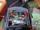
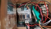
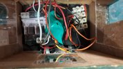
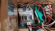
Hopefully someone can help with a few suggestions here. My railcar suddenly stopped working, as in just stopped. After a quick investigation, we found a detached wire, which solved the problem of no movement. Unfortunately we found the the red/white bi-coloured LEDs at both ends failed to work, other than the white lights at one end only light up when the engine has stopped. I've looked at all the cables and can't find anything amiss, but then again I'm only really guessing, no more loose wires etc. Would it be that one of the20251026_193433.jpg electronic boards pictured have blown?
20251026_193446.jpg
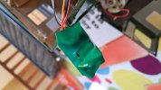
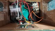
The one with the green cover seems to be a bit iffy, with the marks on the capacitors(?)
 
The installation looks a little 'untidy'. If you can see scorch marks on capacitors, then they will have probably ly popped....
 
Let's give our resident loco-leccy exsquirt a call. PhilP PhilP can you take a look please?
 
In the top photo there is a hole in the heatshrink covering.
I'd be looking at what caused that first.
As Gizzy said maybe something has failed that caused it. Overheating perhaps caused by the detached wire touching something it shouldn't.
 
I see a Brian Jones Mac5 controller. - Which are pretty bomb proof..

Guessing, but the green shrink-wrapped item looks like it was fastened out of the way?
This might be the receiver, but more likely a relay unit to swap polarity to the bi-colour LEDs..

If this is a c/o relay, it is probably controlled by an output on the Mac5. This unit is possibly the weak link in the system.

PhilP.
 
Thanks for your replies. The railcar came to me second hand, and seems to be quite elderly. Perhaps i should really be looking at a total rewiring, because as said it's a bit untidy in there, and i think the batteries may be on their way out. Not some thing to look forward to.
 
I see a Brian Jones Mac5 controller. - Which are pretty bomb proof..

Guessing, but the green shrink-wrapped item looks like it was fastened out of the way?
This might be the receiver, but more likely a relay unit to swap polarity to the bi-colour LEDs..

If this is a c/o relay, it is probably controlled by an output on the Mac5. This unit is possibly the weak link in the system.

PhilP.
I'm pretty sure the Mac-5 will deliver directional lights, so, even with bi-colour LEDs do we really need a relay ;)
 
I see a Brian Jones Mac5 controller. - Which are pretty bomb proof..

Guessing, but the green shrink-wrapped item looks like it was fastened out of the way?
This might be the receiver, but more likely a relay unit to swap polarity to the bi-colour LEDs..

If this is a c/o relay, it is probably controlled by an output on the Mac5. This unit is possibly the weak link in the system.

PhilP.
I thought I put a comment in here, but I can't see it - so here goes a repeat (just in case)

I think the Mac5 delivers directional lights, so is a relay really needed.

Or, have I simply got standard LEDs wired to the same outlet in opposite polarities :think::think::think: I have a Mac5 in Big Bertha and the memory is fadin........................... :worried:
 
I think the Mac5 delivers directional lights, so is a relay really needed.
It's complicated.. :D

I am not sure if they are 'logic' type outputs (so a V+ when on, and 0V when off) or more-likely transistor switches (connection to ground, 0V when on, and open-circuit when off)..

If the latter, then yes, a relay wired as a DPDT changeover (reversing) switch will be needed to reverse the polarity to a two-wire bi-colour LED.

The wiring is a bit untidy, so difficult to work out what everything is doing.
If the OP can provide more information, it should be possible to provide guidance and diagnose the fault. - Don't 'just rip everything out' without working out which the main feeds and components are!

PhilP.
 
P Paul M it might be an idea to gently move things apart and take more pictures, I would be inclined to take half a dozen or so and concentrate on one section per shot. As PhilP PhilP says more information is needed but a picture says blah blah blah and I don't suppose a handbook is available. Also if you do rewire everything then a pictorial reference would be helpful to look at when absolutely nothing works.
How do you know all of this pugwash?
It's a car.

emoticon-hands-up jpg.jpg
 
Thanks for your replies. The railcar came to me second hand, and seems to be quite elderly. Perhaps i should really be looking at a total rewiring, because as said it's a bit untidy in there, and i think the batteries may be on their way out. Not some thing to look forward to.
I'm pretty sure the Mac5 terminals are labelled - that's probably a big help. if not, I'm sure that if Brian Jones is still making them, he'd send a copy of the instructions.

Don't know if I still have my Mac5 instructions :think::think:
 
I'm pretty sure the Mac5 terminals are labelled - that's probably a big help. if not, I'm sure that if Brian Jones is still making them, he'd send a copy of the instructions.

Don't know if I still have my Mac5 instructions :think::think:
Oh I think I have a Mac5 Brian Jones job in one of my beasts, NO it is a FX4U sound card (but with the instructions nicely filed) driven by a Crest system.
 
Thanks for all your replies, I'm going to look further into it, as has been stated, its a bit of a spaghetti meal in there, and not really knowing anything about electronic gubbins I'm at a bit of a loss! I'll do as suggested and take some more pictures. I dont suppose the chap I bought the loco from will still have any diagrams of what was done, and he isn't really around much to ask at present.
 
Thanks for all your replies, I'm going to look further into it, as has been stated, its a bit of a spaghetti meal in there, and not really knowing anything about electronic gubbins I'm at a bit of a loss! I'll do as suggested and take some more pictures. I dont suppose the chap I bought the loco from will still have any diagrams of what was done, and he isn't really around much to ask at present.
If you can find the time you are very welcome over here to see what we can do with it. I tidied up a very tight installation in one of my very small G3 locomotives a while back to good effect. May not look that good but if you saw the spaghetti jungle when I bought it, well nuff said.image.jpg
 
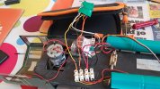
Yesterday I managed to pluck up courage, and managed to find the well concealed screw that held most of the body on and I tidied the wiring as bet as I could, it looks a bit easier to see. Unfortunately it doesn't actually mean I can see what the problem is! The 2 black patches on the green cover, look like the capacitors may have pushed through, but whether that was caused by the problem or whether its always been like that, I can't say. Another thong I found, which is probably more concerning, the loco didn't always stop when the joystick on the controller was pushed to stop. I had to turn of the batteries at the loco. After that it was fine. I've taken some more pictures which may help.
Jon, I may well take you up on your kind offer, I'm a bit lost with electronic stuff, give me 415volts anx decent sized wires any day!
20251101_114320.jpg20251101_115745.jpg20251101_112850.jpg20251026_193446.jpg20251026_193433.jpg
 
Yesterday I managed to pluck up courage, and managed to find the well concealed screw that held most of the body on and I tidied the wiring as bet as I could, it looks a bit easier to see. Unfortunately it doesn't actually mean I can see what the problem is! The 2 black patches on the green cover, look like the capacitors may have pushed through, but whether that was caused by the problem or whether its always been like that, I can't say. Another thong I found, which is probably more concerning, the loco didn't always stop when the joystick on the controller was pushed to stop. I had to turn of the batteries at the loco. After that it was fine. I've taken some more pictures which may help.
Jon, I may well take you up on your kind offer, I'm a bit lost with electronic stuff, give me 415volts anx decent sized wires any day!
View attachment 349324View attachment 349325View attachment 349326View attachment 349327View attachment 349328
You will be very welcome.

What occurs to me on this installation and I think we are all guilty of it is to keep fitted wires to their full length. What happens is that we (not of course you in this instance) wire things up as they come thus being happy when the thing works after adding new wires required often too long we rarely go back after fitting things in place and thus tidy up the wires when it all works. I am equally guilty of this. I can see that shortening wires one at a time, refit with no constant jumbling of over and under wires will help to make the installation look much tidier and likely make bug sorting much easier.
 
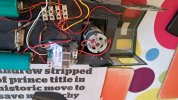
Those pictures make things a lot clearer..
The second picture being the most helpful:

The 3-wire cable disappearing off to the right, is the control and power, from/to the receiver. - The speed controller supplies 5V to the receiver.

The right hand section of the screw terminal block, is battery power. This feeds the bigger screw terminal block (top right) on the Mac5.
There are two thinner wires, feeding power to the green shrink-wrapped switcher/relay unit.
Output from this is the orange/yellow wires to the left hand section of the screw terminal block. Wires from this go fore and aft to the LEDs.
The 'control' for this is the two wires from the smaller green screw terminals on the Mac5.

The larger pair of screw terminals on the left of the Mac5 are the motor outputs.


You say you don't have a 'stop' position on your transmitter?
Is this a centre-off, or do you control direction with a second stick?
I think it should be centre-off, and you should be able to adjust a trim control to give you a 'stop' which matches the stick central position. - Failing this, it will be a case of seeing if this can be set on the Mac5.

Lights:
If one light is working, and changing colour, then the switcher is working and there is a fault in the wiring to the second light, or it has failed.
If one (or both) lights work in only one direction, then there could be a fault in the switcher..
But... I would get the speed / direction right first, as this will affect at what point the lights swap over.

PhilP.
The transmitter is aircraft toggle type with centre off. Left and right forward and reverse. That usually works fine, just occasionally it wont turn off the motor when it's in the off position.
One set of lights show white when the loco is turned on , but goes out when either direction is chosen. Ive gone through the wiring the best i can, but it all seems to be connected properly, so im assuming its either the Mac5 or the relay, but which one is beyond me unfortunately.
 
Sounds like the relay unit?
The Mac5 are pretty bomb-proof usually.. - I expect it will be a cheap bought-in unit?

Let me see if I have any Mac5 instructions squirrelled away..

PhilP.
 
Back
Top Bottom