How do I wire a double-entry return loop using LGB1015T/K track components?

The mechanic

Registered
Country flag
Hello everyone,

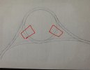
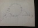
As part of my new garden layout I have laid an LGB rad3 circle with six points, to form a double return loop. I.e. A loop which allows reversing from each end (the diagram in the picture attached explains more clearly)

I run analogue DC via an Arisocraft train engineer (G scale version)

I would like to use LGB 1015T and 1015K track units to provide a one-way system around the loop. The problem is, I don't really know where to put each track unit (T or K). All of the wiring diagrams I have found, only show wiring for a single-entry loop.

Could some kind knowledgeable person please indicate on my drawing where to put the units to enable analogue operation? I would be most grateful

Thanks in advance

Daveimage.jpg
 
Actually it is a little more complex than one might imagine. Look at my diagram below, conflict arrises with voltage in the locations I have filled in with red boxes.
AE201492-932B-44F5-80F0-BB6F8E7A4B00.jpegThus a train perambulating left to right or right to left at the lower or top of the section creates no conflict of power. Now if this layout is in curves as shown the 1015t and k will be of no use, however should there be space for them then a set of each in each box would be fine. it would not matter which way the perambulation round the conflicted loops were set up so long as you understood that trains via the confliction always need to go the same way, must stop and the controller be reversed and that any long locomotive or railcar set must sit entirely between the 2 isolation sections.
 
Thanks for this Dunny. Really got me thinking now, if I can't physically get a 1015T or K into the rad 3 curves, how hard would it be to build my own? Do you know of a circuit diagram and diode values that are required. Could be a good "Brownie point" with SHMBO too as those track sections can be expensive

Dave
 
first thought...
you must decide if to use the "double-loop" clockwise or counterclockwise - but it must be the same for both entries.
then i would put two pairs of 1015T and 1015K track - one pair each on the right and on the left beetween the outer switches and the circle.
Thanks for the help Korm. Just got to get my head around it now!

Dave
 
Speaking as someone with little experience of such things, could you not cut the track and have the "gubbins" housed outside it and wired into it? Not very clear but I think you will know what I mean. (In fact, Gaugemaster appear to do something like this or smaller scales - Prodigy Auto Reverse Loop Module-Gaugemaster-DCC40)
Ah yes Playmo, but you have mentioned the three unmentionables .... DCC!

We are " The analogue party" here, and it is like V*^lderm#rt , we cannot and dare not, speak its name!
 
Thanks for this Dunny. Really got me thinking now, if I can't physically get a 1015T or K into the rad 3 curves, how hard would it be to build my own? Do you know of a circuit diagram and diode values that are required. Could be a good "Brownie point" with SHMBO too as those track sections can be expensive

Dave
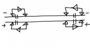
It would be quite simple you just need to have isolations on both rails at 2 locations, you could use the location of the existing rail joiners at the beginning of the loops (remembering my red box sections earlier) and solder up Diodes as below. I am not sure which way round this would makes trains go under analogue, depends on what line is positive. However checking with a meter the reversing the controller will tell you this. I used 1N5401 diodes for the job, they are good and chunky and should be just fine. You can get 10 from Ebay at less than £2 so much more cost effective that LGB.
68FEBD77-F4C7-4363-903E-0EF7211E70C1.jpeg
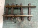
if you do not have a chunky Soldering Iron you could wire them up to Massoth or anyones screw terminal Isolating Fishplates like below. Not a pretty set up but just knocked together to show the concept. Note how the diodes are different ways round as shown by the silver ring which shows where the positive current is blocked from passing the Diode.
92326A4E-8E14-451A-8F40-386C266BAAEF.jpeg
With your setup even with 8 x Massoth Isolating Fishplates and 8 diodes you would get your 2 reverce sections much cheeper than the LGB track sections you proposed using.
 
Ah yes Playmo, but you have mentioned the three unmentionables .... DCC!

We are " The analogue party" here, and it is like V*^lderm#rt , we cannot and dare not, speak its name!
It would be quite simple you just need to have isolations on both rails at 2 locations, you could use the location of the existing rail joiners at the beginning of the loops (remembering my red box sections earlier) and solder up Diodes as below. I am not sure which way round this would makes trains go under analogue, depends on what line is positive. However checking with a meter the reversing the controller will tell you this. I used 1N5401 diodes for the job, they are good and chunky and should be just fine. You can get 10 from Ebay at less than £2 so much more cost effective that LGB.
View attachment 272156
if you do not have a chunky Soldering Iron you could wire them up to Massoth or anyones screw terminal Isolating Fishplates like below. Not a pretty set up but just knocked together to show the concept. Note how the diodes are different ways round as shown by the silver ring which shows where the positive current is blocked from passing the Diode.
View attachment 272157
With your setup even with 8 x Massoth Isolating Fishplates and 8 diodes you would get your 2 reverce sections much cheeper than the LGB track sections you proposed using.

Dunny you sir, are a diamond! Thank you for taking the time to explain this in terms that I can fully comprehend.
If I can ever reciprocate, I will not hesitate!

Thank you for this

Dave
 
Ah yes Playmo, but you have mentioned the three unmentionables .... DCC!

We are " The analogue party" here, and it is like V*^lderm#rt , we cannot and dare not, speak its name!

Oops. missed that! I, too, am all for analogue. Indeed, I've only just accepted the need for electric points.
 
I'd better not mention wireless-control, and happy-hippy sloar-charged batteries then? :eek::eek::shake:
 
I assume you only run one train at a time. Otherwise you're going to have unintended reversing locos that are not in the loop. (Pun not intended;))
 
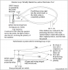
Skip the electronics. Just make up a couple of these and place them at the two exit points. You need to cut the running rails, and depending on the make of your points you may have to gap the closure rails as well. This is unlikely with most proprietary pointwork. Look for a more detailed description of this on page 1 of the thread "Fully Automated Reversing Loops" on this site. Cheers.

1598713531262.png
 
Back
Top Bottom