Help on POLA 1946 Turntable

AMuller396

Registered
Country flag
Hi,

I recently got hands on this G Scale turntable.

I’m trying to test and see if it works but am having a bit of trouble due to my “inept” ability in electronics and anything electrical.
DB6A985D-F2AD-43AC-9033-8D7E9334AD6A.jpeg
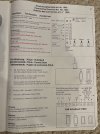
The instructions provided above shows how to connect it all together.

I know X1 and X2 should be connected to 20v AC which I have connected to LGB 50111.

X3-X6 should be connected to the wiring for the included control panel.
5D302085-48AC-47DC-89E9-898E878DA99F.jpeg

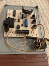
However, the cable for the control panel has 6 cables with X4 X5 X6 has yellow red and black inserted respectively. That leaves me with X3. There are 3 cables not attached orange brown and one with no jacket.

Anyone know which cable should go to what?

If I go with the 51800 it says to hook it up to a max 1amp AC transformer, so that seems my 50111 would be out of the picture?

The instructions for 51800 depicted above shows X3 and X4 to the far left of 51800 but that’s the input for the power on 51800 depicted with symbol 1*2 or 3*4 (LGB AC or dc). If that’s what they want how do I connect that 51800 to a 1 amp AC transformer?

Does anyone know if this item is suitable for outdoors year round? Southern California weather.

Also, If I decide to hook this up as a digital hook up what does one need to do?

Any other tips you might have for those that already have this item?

Thank you very much and I apologize if this was very trivial.

Andrew
 
Let me begin by saying that I do not have one of these. That said, I think you are misinterpreting how the LGB 51800 is being powered.

The 51800 does not get connected directly to your transformer/power supply. The turntable control circuit board contains a rectifier and power conditioning that converts the AC input power on X1 and X2 to DC output power on X3 and X4. That is why X3 and X4 are connected to the power input connections on the 51800. X3 and X4 are supplying the power. Also, the instructions explicitly warn against connecting the 51800 to any other source of power except the X3 and X4 outputs of the turntable circuit board! That is what the "Attention:..." at the bottom of the instruction page means. So do not daisy-chain the 51800 controlling the turntable with any other 51800 control boxes you may have. Keep it separate.

The dashed lines delineating the two right switches of the 51800 from the two left switches that control the turntable indicate that the right switches may be used to control other items of your choosing that use DC power. But the maximum combined DC current draw on the two right switches must not be more than 1 amp otherwise the current capacity of the turntable circuit board will be exceeded. Also, the right two switches cannot be used to operate motors. The output voltage at the two right switches is shown as 16-20V DC because the actual DC voltage available is dependent on what AC voltage (16 - 20 VAC) is connected to X1 and X2 on the turntable circuit board.

Hope this helps.
 
Last edited:
We had one of these on the Ruschbahn and I concur what Phil has said re electronics.

As for operation, the one we had was outside full time, near conifer trees and had some issues.

First very quickly the powered working failed due to the gears that moved the table round were totally unfit for purpose. Was great when working but look at the small gear on the motor, not much bigger that you would use to drive an N hauge locomotive.

Then there are the contacts to the track, these slide along to make contact from the table to exit/entry sidings. These get bent if there is any detritus that gets into the sliding part.

Finally there are ball bearings inside with curved plastic sections between them, these plastic sections again get mixed up with detritus and can get broken.

Best advice I would give would be to make some kind of cover (even if not near trees, birds can deposit all sorts of detritus) so that between operating sessions as much detritus as possible can be kept out of the working mechanism. This way you should get some happy and hopefully long term use out of this attractive unit.
 
I have one. Its as stated above. Connection that is.
i also connected a low voltage dc throttle directly to the motor leads and indexed manually until i figured out the wiring.
it worked actually quite well, if inelegantly.

i used mine for about a week. Then i got fed up. Still as new, but rather fiddly…bronze connectors, ball bearings, etc.
imho, only for indoor use, and sparingly at that.

these sell on ebay for ridiculously high prices. If only the buyer knew what they actually are.

good luck
 
Let me begin by saying that I do not have one of these. That said, I think you are misinterpreting how the LGB 51800 is being powered.

The 51800 does not get connected directly to your transformer/power supply. The turntable control circuit board contains a rectifier and power conditioning that converts the AC input power on X1 and X2 to DC output power on X3 and X4. That is why X3 and X4 are connected to the power input connections on the 51800. X3 and X4 are supplying the power. Also, the instructions explicitly warn against connecting the 51800 to any other source of power except the X3 and X4 outputs of the turntable circuit board! That is what the "Attention:..." at the bottom of the instruction page means. So do not daisy-chain the 51800 controlling the turntable with any other 51800 control boxes you may have. Keep it separate.

The dashed lines delineating the two right switches of the 51800 from the two left switches that control the turntable indicate that the right switches may be used to control other items of your choosing that use DC power. But the maximum combined DC current draw on the two right switches must not be more than 1 amp otherwise the current capacity of the turntable circuit board will be exceeded. Also, the right two switches cannot be used to operate motors. The output voltage at the two right switches is shown as 16-20V DC because the actual DC voltage available is dependent on what AC voltage (16 - 20 VAC) is connected to X1 and X2 on the turntable circuit board.

Hope this helps.
OMG - your explanation is spot on! I had to re read the instructions again and the way you explained it made a lot more sense. Thank you. Ill try and see if it works using a 51800.
Also, I went to Faller's website and saw that there is a different set of instructions for this unit than what was provided. The one on the website is far more clear, however it still doesn't show how to connect the included "control desk" wires to the unit.

We had one of these on the Ruschbahn and I concur what Phil has said re electronics.

As for operation, the one we had was outside full time, near conifer trees and had some issues.

First very quickly the powered working failed due to the gears that moved the table round were totally unfit for purpose. Was great when working but look at the small gear on the motor, not much bigger that you would use to drive an N hauge locomotive.

Then there are the contacts to the track, these slide along to make contact from the table to exit/entry sidings. These get bent if there is any detritus that gets into the sliding part.

Finally there are ball bearings inside with curved plastic sections between them, these plastic sections again get mixed up with detritus and can get broken.

Best advice I would give would be to make some kind of cover (even if not near trees, birds can deposit all sorts of detritus) so that between operating sessions as much detritus as possible can be kept out of the working mechanism. This way you should get some happy and hopefully long term use out of this attractive unit.

Thank you for the feedback. I guess Ill just remove it from the garden every time when not in use.

I have one. Its as stated above. Connection that is.
i also connected a low voltage dc throttle directly to the motor leads and indexed manually until i figured out the wiring.
it worked actually quite well, if inelegantly.

i used mine for about a week. Then i got fed up. Still as new, but rather fiddly…bronze connectors, ball bearings, etc.
imho, only for indoor use, and sparingly at that.

these sell on ebay for ridiculously high prices. If only the buyer knew what they actually are.

good luck

Lol, I guess I got suckered in to buying one on ebay :worried:

Anyone know how to connect the included control unit wires to the appropriate X3 - X6?

How about converting this to digital operation, any one know what would be needed?

Thanks again
 
Last edited:
As an aside, the 20V ac input will be rectified and filtered to DC and the voltage will be 1.4 times the AC input... so your DC could be 28 volts...

(note the standard full wave bridge (silicon diodes) and electrolytic filter capacitor.

Greg

Thanks Greg. I wish I know what you mean, everything what you said was like Chinese to me. But what I gather and I'm guessing here, is that IF I use the remaining slots on the 51800 to connect to something it would be at 28VDC. Just use the 51800 dedicated to the turntable.
 
Regarding DCC operation, I doubt it would be possible to use it that way and have different roads indexed. However if the motor was powered by a small cheep chip like a locomotive it may be possible. No doubt someone will comment on the logic of that. There is someone your side of the pond that no doubt will.
 
Reading the Nov/Dec issue of Garden Railway news as covered by Tac tiday, I noticed that Split Jaw are to offer a Battery Operated Turntable in 3 sizes. One of these may be a better bet and flog your Pola one on to some other unfortunate. Ouch just looked at the split jaw TT price! Possibly not.
 
I also noticed that their site states the rails are unpowered and the table is only suited to battery or live steam locos.
As it is all aluminium, I would guess there would be a dead-short, across the rails?

There custom large scale consists, make the eyes water...
LGB F7 ABBBA anyone?
$4k plus. :eek:
 
What I say to people I mentor at work is:
"It's better to ask than be an a**e."
If you don't know something, you don't know it, so unless you ask you won't ever know


As folks have said many times on here, the only stupid question is the one that you DON'T ask.... ;)

Jon.
 
we call them cell phones here as well as mobiles.

at least we don't confuse the word for cigarette!!!

Greg
:rofl:

thanks for the help guys.

I haven’t had the chance to tinker to make it work since I’m on holiday for the weekend, but was thinking about how does this thing work on analog operation.

7DED2FC8-E17D-4D0C-88AB-0179C453AE9A.jpeg

Above is what I thought about how this thing is powered, but maybe I’m wrong.

Track A and C are on a on off 51800 connected to the transformer and I assume the power on the turntable track itself will come from Line A or C since they will be in contact with the brass fittings.

Track B is lined up with the main track so it’s powered when lined up.

Is this how it should work, or is there a better way? Easier way?

Thanks a lot guys

Andrew
 
I've had limited experience of turntables, not this one either, and only indoors. IMO it would be very hard to get one to work under motor control reliably outdoors due to all the problems mentioned. You may have to resort to manual control which would at least make lining up the roads easier!

My indoor experience (with DCC on OO/HO) is with a Hornby turntable and a home made traverser (not a turntable but similar principle). The Hornby turntable as supplied only provided power to the turntable track when it was lined up to one of the roads. If you were using DCC sound locos and you wanted light and sound to stay on when the loco was turning, you needed to modify this to provide power to the moving track directly and invest in a DCC reverse loop module to handle the polarity change when the loco reversed. The movement was provided by a simple electric motor which you turned on and off with a switch like your 51800 to line up the roads. However to make this a bit easier the Hornby turntable had a large driving cog with some missing teeth so there was a "dead zone" of a few seconds when the motor was running but the turntable did not turn. This made it much easier as you did not need lightning reactions to stop the turntable in the right place! To control this under DCC required some software which would run the motor for a predetermined number of seconds - say 10 seconds to move from road A to B - which was arrived at by trial and error - but it worked quite well. With my home made traverser I used a system of micro-switches to ascertain when the motor had moved the traverser far enough which did away with the need for manual dexterity. And as the traverser did not reverse the locos there was no need for a DCC reverse loop module.

I hope this gives you some ideas even if is a bit of a tangent.

Thanks for the info. I was thinking that if I equip most of my engines with LGB 55429 that would solve the no power light and sound when turn table is turning.

Anyways, I have connected the item using the 51800 and connected the wiring per the instructions and tips from above. The light turns on! But the motor doesn’t move :( Neither direction.

Also just connecting it to power and running under “TEST” the light comes on but the motor doesn’t move.

I’m sure someone with a lot more electronics experience can make this work, but now I’m thinking of just returning it from the person I bought it from. Looks like from comments above this thing is just problematic and hard to use.

Thanks

Andrew
 
Back
Top Bottom