Help Needed - Decoder Wiring 2

David1226

Registered
Country flag
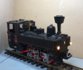
Many years ago I acquired a 1988 vintage LGB 2070D analogue U-Class, U43, rear bunker version in grey.
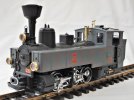
dig 210704019.JPG

I have carried out several cosmetic changes, including spraying it black, and I now need to fit a decoder. This model is of the three pin connection, pre-digital, type, which I now need to convert to four pins before I can fit a decoder. I am aware of the electrical alterations required to the gearbox to isolate the combined track/motor feed and add a fourth wire in order to provide two track feeds to the decoder and two decoder feeds to the motor.

My problem is that I can find no obvious way of accessing to top of the gearbox and the motor. I am aware that there is an article of converting an old style U-Class, on the Forum, but this is of an even older style U-Class and is of no help to me for this model.

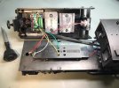
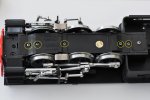
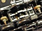
Removing the five screws to remove the bottom of the gearbox only gives access to the gears/axels/pickups which I was hoping not to have to disturb.
dig 220304001.JPG

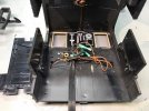
dig 220303001.JPG

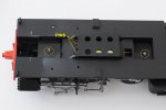
I have studied an on-line exploded parts diagram and it would appear that there are two screws that hold on the top of the gearbox. The rear screw is plainly visible/accessible, but the front screw is covered by part of the frame moulding.
dig 220304002.JPG

My questions are, is there anyone out there who has already carried out this conversion and can advise me. Is there a relatively simple way to access the gearbox top and motor in order to modify the electrical connections, without having to dismantle/remove the contents of the gearbox/wheels/valve gear. Is anyone aware of any on-line articles that would help with this conversion.

Thanking you in anticipation.

David
 
Can't help with a Forum thread, but you will need to drop the motor-block off the loco.

From memory, two of the screws through from the bottom, will be longer, and it is these that hold the 'block.
I *think* you have to drop the cylinders with the' block, on this model?

It is quite some time, since I have had one apart, though, so wait for comments from others, perhaps?

PhilP
Phil

Yes, I am hoping there is some way of dropping the whole motor block out. I know the two longer screws you are referring to.

David
 
David the LGB breakdown diagram should help you, I have looked at my LOK book for you and the ref would appear to be 2070D (20701 is the later ref for this loco). Hope that helps.
 
Update

I have succeeded in dropping out the gearbox/wheels/valve gear in one unit, removed the top of the gearbox and removed the motor. The internals are nothing like I was expecting, no wires, just contact strips. I now have to puzzle out where I need to sever contacts and create a new one.

David
 
Update
The internals are nothing like I was expecting, no wires, just contact strips. I now have to puzzle out where I need to sever contacts and create a new one.

David
David, those three pins in your last image are the key. One connects to one side of the track and the other on the same side of the loco to one side of the motor. The third pin, on the other side of the loco, connects to both the other side of the track and the other side of the motor.
Common practise is to bend the brass strip on the motor that touches this third pin away from the pin. Solder a wire to this motor brass strip and insulate it so that it can no longer make contact with the pin. Reassemble the motor block with the new wire exiting via an existing hole or one you choose to drill. You will then have the four main connections you need, three pins and a wire. One each to each side of the track and one each to the motor terminals.
The smoke unit and light connections should be straight forward but pay attention to their voltage rating and adjust the decoder accordingly.
Neil

Many thanks for that.

David
 
Many years ago I acquired a 1988 vintage LGB 2070D analogue U-Class, U43, rear bunker version in grey.

View attachment 295870

I have carried out several cosmetic changes, including spraying it black, and I now need to fit a decoder. This model is of the three pin connection, pre-digital, type, which I now need to convert to four pins before I can fit a decoder. I am aware of the electrical alterations required to the gearbox to isolate the combined track/motor feed and add a fourth wire in order to provide two track feeds to the decoder and two decoder feeds to the motor.

My problem is that I can find no obvious way of accessing to top of the gearbox and the motor. I am aware that there is an article of converting an old style U-Class, on the Forum, but this is of an even older style U-Class and is of no help to me for this model.

Removing the five screws to remove the bottom of the gearbox only gives access to the gears/axels/pickups which I was hoping not to have to disturb.

View attachment 295873

View attachment 295876

I have studied an on-line exploded parts diagram and it would appear that there are two screws that hold on the top of the gearbox. The rear screw is plainly visible/accessible, but the front screw is covered by part of the frame moulding.

View attachment 295877

My questions are, is there anyone out there who has already carried out this conversion and can advise me. Is there a relatively simple way to access the gearbox top and motor in order to modify the electrical connections, without having to dismantle/remove the contents of the gearbox/wheels/valve gear. Is anyone aware of any on-line articles that would help with this conversion.

Thanking you in anticipation.

David
The first thing is to try to find the LGB Parts Diagram which can be very helpful in assessing how to disassemble and reassemble a locomotive. The OnlyTrains.com site has a good inventory of both the locomotives' User Guides and Parts Diagram........the 2070D is there. There's a video on my Website's Homepage, third one, of an LGB 2072D DCC sound conversion I completed for a customer. As I recall there were screws on both the bottom and top of the motor block to remove in order to remove it. These older LGB models did not have a circuit board with the regulators for 5v. lights and smokers, but instead 18v. lights and smoker and only a diode to activate the lights in only the forward position. I installed an ESU 5XL DCC sound decoder into the boiler but had to cut two of three lead weights for the fitment.
 
I installed a Zimo MX 696 recently into one of these and external power buffer, bit of a squeeze but didnt have to modify any on the ballast weights.
 
I installed a Zimo MX 696 recently into one of these and external power buffer, bit of a squeeze but didnt have to modify any on the ballast weights.
Hi gn13565 - Sure, it all depends upon which components you elect to install. In the LGB 2170D locomotive, my customer requested I install the ESU 5XL, which I consider the best on the market for LGB locomotives, and it's fairly large, so I had to slice up and rearrange the lead weights. I also was able to install a 40mm speaker inside the firebox with some Dremel work and then sealed into position using epoxy putty. The installation configuration is shown below, including the 40mm speaker. I also removed all the unreliable factory brass strips to the rear lights and instead rewired them. If you'd to hear the wonderful operating sounds produced by the ESU 5XL sound decoder in this locomotive, go to my Website's Homepage, at the bottom are several demo videos of installations I've done on customers' LGB locomotives.
LGB 2071D 5XL Install Test Stand.pngLGB 2071D 5XL Install -1.jpgLGB 2071D 5XL Install -2.jpg
 
Hi Tom
That sounds like you did a great job.
The one thing I struggled with was the speaker. I fitted a flat speaker, but am disappointed in its quality. I might open up again and try your solution.

Re decoders I use a mixture of ESU and Zimo. Really happy with both.

Kind regards
Greg
 
Hi Tom
That sounds like you did a great job.
The one thing I struggled with was the speaker. I fitted a flat speaker, but am disappointed in its quality. I might open up again and try your solution.

Re decoders I use a mixture of ESU and Zimo. Really happy with both.

Kind regards
Greg
Greg - Yes, the speaker installation can make or break the quality of a locomotive sound installation.

I've never tried the Zimo decoders, I'm sure they're good German quality like the ESU. The ESU has a huge locomotive sound library with excellent sound qualities.......most of the sound files have 30 F Key activation options.......amazing. I'm a dealer and installer for ESU, Massoth, Soundtraxx, LGB, Marklin, and MD-Electronics DCC decoders and accessories and will also install Phoenix Sound decoders but not a dealer. I'd say the Soundtraxx is the next best sound and about as complex as the ESU, but many of the sound files used in Marklin-produced LGB locomotives with their MSD3 mfx/dcc/analog decoders are also very good and quite complex........unfortunately their F7A Diesel sound file is okay but can't match the ESU F7 sounds.
 
Dave, this thread may be of some help. It includes some pics of my conversion using an ESU Lokpilot V4.0.
 
Back
Top Bottom