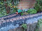
Garden railway version 3.0

natdawson

Registered
31 Oct 2009
31
40
Best answers
0
Country flag
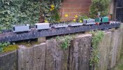
After having to lift my second garden railway due to a number of reasons I needed somewhere I could at least run a battery loco and some wagons. We are very limited for space but a possibility was on top of a small narrow raised bed for at least a short end to end railway.
Giving it some thought and the with the knowledge that 0-4-0 Roundhouse battery loco chassis and wagons I have will go round 24" diameter curves without any difficulty the possibility of at least one return loop if not two was worth looking at.

With no budget to speak of I found myself with a load of effectively third hand Peco G45 flexi track, some hardwood faced ply and a need for a railway.

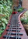
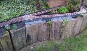
Starting at one end with a return loop of 22" diameter I set about seeing what would fit in the space available and ended up with a complete loop, featuring two tight return loops and a section of interlaced track due to lack of points and a sense of why not.
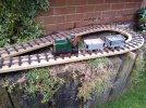
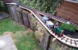
1.jpg

2.jpg

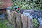
After temporarily laying the track of the ply track bed everything was lifted so that some wood stain protection could be applied to all of the ply and cut ends of the old fence posts used as supports.
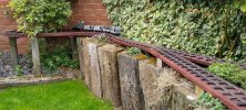
10.jpg

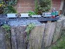
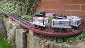
The track was then re-laid and after the inevitable fettling all locos and wagons ran happily round the loop including the interlaced section.
15.jpg

Even with some overly tight curves everything works fine, even when loading with slate and other random stones. Bar couplers greatly improve performance due to the elimination of bunching up and snatching of coupling.

When the warmer weather returns there are a number of scenic improvements I want to carry out including providing some form of slate fence to the track bed and ballast to give it a more natural look as well as some more sympathetic planting to further blend the railway in to the garden.
Not sure what to do with the elevated loop as something like a full on viaduct here would just wrong in the garden.

So far it has cost me about £10 for a fence post which isn't too bad at all until I was then given a couple for free afterwards which was somewhat annoying.
 
  • Like
Reactions: 1 user

PhilP

G Scale, 7/8th's, Electronics
5 Jun 2013
33,605
3,525
Nottingham
Best answers
0
Country flag
Well done for getting tight curves, and interlaced points working.
Your railway empire may not be the biggest, but appears to be to a high standard.

Enjoy!
PhilP.
 
  • Like
Reactions: 1 users

playmofire

Registered
23 Oct 2010
8,279
855
80
North Yorks
Best answers
0
Country flag
Very creative and well executed.
 
  • Like
Reactions: 1 user

natdawson

Registered
31 Oct 2009
31
40
Best answers
0
Country flag
Well done for getting tight curves, and interlaced points working.
Your railway empire may not be the biggest, but appears to be to a high standard.

Enjoy!
PhilP.
Thank you, the curves were a bit of a pain due to having to take all of the sleepers off to put a bend in the rail but now it's done it was definitely worth it to be able to leave a train running round in the background.
 
  • Like
Reactions: 1 user

Paul M

Registered
25 Oct 2016
11,919
1,700
61
Royston
Best answers
0
Country flag
How did you interlace the track?
 

natdawson

Registered
31 Oct 2009
31
40
Best answers
0
Country flag
How did you interlace the track?
By being daft. Ideally I would have used timber sleepers the appropriate length and spiked the rail but this wasn't an option this time.
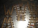
If I remember rightly I took one rail out of a length of Flexi track, increased the sleeper spacing to suit the 7/8ths look better and fixed it to the base board. Any webbing between sleepers was also removed.

A second piece of single rail Flexi track was then fitted with the two rails close to each other. The other rails were then slid into place which was a bit fiddly but worked ok.
Frogs and check rails were then installed at each end of the interlaced section where the track diverged in separate directions.

I'll try and get a couple of pictures when I'm at home. Eventually the sleepers will be ballasted so won't look quite so odd.
 
  • Like
Reactions: 1 user

natdawson

Registered
31 Oct 2009
31
40
Best answers
0
Country flag
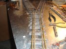
This is a different view of part of the interlaced section which was in the process of being re laid after applying protection to the base boards. Hopefully that will make it a bit clearer.

18.jpg

As I said, I would have preferred to have used longer wooden sleepers and spikes but I had to use what I could. Hopefully when it's ballasted it'll blend in a bit better.
 
  • Like
Reactions: 1 user

playmofire

Registered
23 Oct 2010
8,279
855
80
North Yorks
Best answers
0
Country flag
This is a different view of part of the interlaced section which was in the process of being re laid after applying protection to the base boards. Hopefully that will make it a bit clearer.

View attachment 321591

As I said, I would have preferred to have used longer wooden sleepers and spikes but I had to use what I could. Hopefully when it's ballasted it'll blend in a bit better.
Ah, I see what you mean now; that's really cunning!
 

playmofire

Registered
23 Oct 2010
8,279
855
80
North Yorks
Best answers
0
Country flag
Would that approach work with a track powered loco?
 

PhilP

G Scale, 7/8th's, Electronics
5 Jun 2013
33,605
3,525
Nottingham
Best answers
0
Country flag
Would that approach work with a track powered loco?
Yes.. There are two pairs of rails.

A dead frog would be easiest, but there are ways to detect/switch frog polarity automatically.

PhilP
 

natdawson

Registered
31 Oct 2009
31
40
Best answers
0
Country flag
did you build the frogs yourself, or did you vandalize factory-made parts, like i did?
Bodged them up myself.
I would do it slightly different if I were to make them again as I didn't join both parts with a base which would help a lot with alignment. Still not too bad for a first attempt and can always be modified in the new year.
 
  • Like
Reactions: 1 user

natdawson

Registered
31 Oct 2009
31
40
Best answers
0
Country flag
Would that approach work with a track powered loco?
Other than the actual frogs themselves there is nowhere else the rails join.
Although being in a very tired state due to lack of sleep I'm not sure if you'd actually need to use an insulated frog or not as the inside rails would be the same.
 

Paul M

Registered
25 Oct 2016
11,919
1,700
61
Royston
Best answers
0
Country flag
Looks very good. You may be right about the frog, the inner rail is going to be the same polarity as it goes round.
I seem th remember a magazine article about a 1:1 bridge with rails like that. From what I remember it was because 2 different railway companies couldn't come to running rights or maintenance agreements, they may well have had separate sleepers for each track. If not, it sounds horribly plausible in the weird world of early railway management
 

viaEstrecha

Spanish metre gauge in G scale (on the cheap)
25 Oct 2009
2,145
294
Bedfordshire
Country
United-Kingdom
Best answers
0
Country flag
Looks very good. You may be right about the frog, the inner rail is going to be the same polarity as it goes round.
I seem th remember a magazine article about a 1:1 bridge with rails like that. From what I remember it was because 2 different railway companies couldn't come to running rights or maintenance agreements, they may well have had separate sleepers for each track. If not, it sounds horribly plausible in the weird world of early railway management
I've seen an example in NW Spain, where a bridge's limited structure gauge forced what they term 'suicide tracks'. Very interesting to see it modelled.
 

natdawson

Registered
31 Oct 2009
31
40
Best answers
0
Country flag
Looks very good. You may be right about the frog, the inner rail is going to be the same polarity as it goes round.
I seem th remember a magazine article about a 1:1 bridge with rails like that. From what I remember it was because 2 different railway companies couldn't come to running rights or maintenance agreements, they may well have had separate sleepers for each track. If not, it sounds horribly plausible in the weird world of early railway management
I've seen a few examples, removing moving switch blades will make the setup more reliable in some cases. The Wirksworth railway had a small section installed so they could use an existing loading dock for filling ballast wagons but also a preservation era platform for trains using the incline line.
If you look at the linked picture the track on the right hand side is the interlaced bit to allow both the loading dock and platform to be used, just not at the same time.
Ecclesbourne Valley Railway - Wikipedia
 

natdawson

Registered
31 Oct 2009
31
40
Best answers
0
Country flag
With the weather improving a bit I've finally had the opportunity to do a bit more to the railway in a scenic way. There isn't really much scope for any extension without it being overly complicated and taking up too much room in the garden, the idea being that it blends in somehow and not takes over.

It was never the intention to leave the railway as track screwed down to bare boards, whilst that is operationally fine it does need to blend into the garden and look a more finished article. On a previous railway I have just fixed some wood to the sides of the boards creating a raised edge so that ballast can be kept in place and not fall off.

This worked well until inquisitive children decided to rearrange the ballast at every given opportunity causing numerous derailments. As they have grown up (the kids, not me) having ballast is now a possibility again but due to the sharp loops at each end of the railway there wasn't going to be an easy way to use my old method without it looking like a mess or making custom laminated sections to go round the loops which I don't have the desire to mess around with.

Looking around for possible ideas, I found old pictures of the Corris Railway with slate fences and thought that could work as small pieces of slate fence would easily work going round the loops and could be stuck on with CT1 adhesive.


1.jpg
I experimented with a short section and added some ballast which seemed to work ok. Fitting the slate fence pieces is a very quick process, unfortunately cutting the slate to rough size with a tile cutter and then shaping them to make them look aged took a long time especially with the amount I needed.


2.jpg
With the trial section done I then progressed round the rest of the boards, leaving the adhesive to set for a day before ballasting really changed the look of the railway, however due to the fact that the railway is raised up above the raised bed it still have the look of a floating railway which wasn't ideal.
Some areas would be easier to disguise than others just needing soil raising up to cover the bottom of the slate and some suitable planting but this still left a section of about 1 1/2 meters long where the railway is above the sleeper wall of the raised bed and has no room for a soil embankment.


5.jpg
To try and hide the remaining floating section I decided on a retaining wall made of slate with the added complication of a couple of arches where some plates drape over the side of the raised bed. A lot of mess caused by excess CT1 later and the main central section with arches was coming together. I made this section up inside because of the arches, I wasn't sure how fiddly it was going to get and thought it better to try it in the comfort of the house instead of a cold garden with failing light levels. Once set over night I moved this section outside, made a few modifications so that it sat on the raised bed sleeper ends properly and began to extend the slate wall to the left hand side as far as it was going to go.


8.jpg

Annoyingly I ran out of slate which I had cut into strips before I finished this end but it gives a feel of how it's going to look with the soil embankment to the left which will blend in better once the planting gets established.
The retaining wall will extend further to the right and partially round the corner which will be a bit of a challenge, especially where the slate fencing is flush with the front face of the raised bed for one of the sleepers.


10.jpg

Other than the slight gap above the end of the retaining wall (and the loop to the left which will be dealt with later) the railway has lost its floating look and blends in a lot better than it did before. Hopefully it won't be too long before this section of wall is complete and the new planting begins to spread out and down the front of the raised bed.


15.jpg

The next section of wall retaining wall to the right will be a challenge and will need another but much smaller arch as well but once done should look a lot better and get rid of the floating look at this end on the railway. The middle of the loop was easy to do, just needing the soil level to be built up to a more suitable level. The slate fencing and CT1 should help to protect the edge of the boards from any moisture with the gaps between the slates allowing water to drain off of the boards but preventing the soil from coming into contact with the wood itself.


16.jpg
With the retaining wall and embankment covering the lower parts of the slate fencing they no longer look quite so tall and blend in a lot better as well. Overall although there is more to the railway than before it blends in a lot better and in places look a much more finished article which was the aim. Once I manage to cut a load more slate then I will tackle the remaining third of the retaining wall before figuring out how to make the far loop fit in without resorting to an over powering structure which will look out of place.
I have a couple of ideas on how to address that area but want to get the current section finished first before moving on to it.
 
  • Like
Reactions: 1 user