Dual LGB 10560 electric uncouplers

phils2um

Phil S
11 Sep 2015
1,522
423
Ann Arbor, Michigan
Country
United-States
Best answers
0
Country flag
On another thread I lamented that what I was calling a "drop-in uncoupler" (https://www.gscalecentral.net/threa...-g-scale-interest.310793/page-207#post-615143) was causing a random uncoupling issue on my single mainline. The problem was being caused by the manual uncoupler that is needed in addition to the electric uncoupler to separate LGB symmetric hook and loop couplers. The manual uncoupler is always up which causes the problem. It is not an issue when shunting on sidings - just need to go back and pick up what was mistakenly uncoupled. On the mainline, however, when a train passing through suddenly separates it is a big problem.

I felt replacing the manual uncoupler with a second electric unit would solve the issue. The only hinderance is that two out of the box 10560 uncouplers positioned back-to-back don't have the correct ramp spacing to simultaneously lower the coupler hooks on both wagons. I had speculated that I might end up using an old LGB 1055 twin-coil (three wire) uncoupler I had. I would cut it to fit after replacing the drive with a modern two wire EPL or equivalent. This turned out to be a non-starter. The 1055 uncoupler is a completely different design and not amenable to modification.

A careful look that the current production 10560 uncoupler proved to be the answer. The uncoupler can be disassembled and the uncoupling ramp moved one tie spacing toward the end of the 10150 track section on which it is mounted. See the first pic below.

Uncoupler mod - 1 (9).jpeg

There is a molded protrusion on the bottom the the uncoupler ramp that will keep the ramp from lowering completely. Drilling a hole in the double tie solves the problem.

Uncoupler mod - 1 (2).jpeg

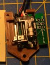
It turns out the existing mounting holes can be used to attach an EPL or similar switch drive to operate the uncoupler in its new position. This drive replaces the uncoupler drive that came with the unit. This was OK with me as only one light post is needed. I actually used a MD Electronics SWD servo switch drive.

Uncoupler mod - 1 (10).jpeg

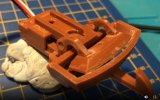
Now comes the only actual modification, read cutting, necessary to make things work. About 3 mm needs to be cut from the frame that surrounds the ramp. This in no way effects the actual operation of the uncoupler. I used a razor saw in a small miter box to trim the ramp frame.

Uncoupler mod - 1 (4).jpeg

Here's a look of the finished modification. Depending on how you want to wire the uncouplers you can stop here.

Uncoupler mod - 1 (5).jpeg

Here's a side view of the uncouplers in action.

Uncoupler mod - 1 (8).jpeg

I took a further step to keep the LGB standard 300mm length DCC "drop-in" feature. I drilled some holes in the ties to run the wires feeding the decoders. Eyes on the leads get the DCC signal and power from rail clamps.

Uncoupler mod - 1 (7).jpeg

I also added a LGB supplementary switch to the unmodified uncoupler. It turns on the light when the ramps are up. The decoders for the two uncouplers have the same DCC switch address. This makes them operate in unison.

Uncoupler mod - 1 (6).jpeg

About the only thing I should have done differently is to drill the wire guide holes for the power leads directly under the rails to hide them better. Will do that on my next one.

One nice thing about this mod is that it can be completely reversed. The bit that was actually cut off has no impact on the operation of the uncoupler should one wish to restore it to the out of the box configuration.

Edit added: See post #9 for an update! Total of 8mm trimmed to improve operation.
 
Last edited:
  • Like
Reactions: 1 users

Dagnall

Registered
17 May 2016
34
15
71
HAYLING island
Best answers
0
Country flag
That looks like a candidate project for a 3d printed version! Especially as you are using my servo drives :)..!!
Can you provide some dimensions ? height above track when activated is probably the most important!..

A bit of a teaser..
I have finished my Stepper motor driven LGB type decoupler project, - but it got a lot of interest from a guy in Germany who hopes to be able to make it into an affordable injection moulded product, so I agreed to hold off publishing the 3D files to give his product a chance..
For myself, I designed a small PCB that drives the Stepper as though it was a servo, and made a version of the PCB that fits this inside the "box".
The "open" photo shows the ICP contacts for programming the board protruding out, but his part can be cut off once it is programmed, to make the "box" smaller".
However soldering the stepper filmwire to the PCB is an absolute PIG.!!! (its done blind, and the contacts are tiny.. S o the "production version" will have 4 simple wires to a small external PCB supplied by the German guy that you can hide in the engine.

Cheers
Dagnall
 

Attachments

  • Screenshot 2021-07-24 172426.jpg
    Screenshot 2021-07-24 172426.jpg
    124.4 KB · Views: 0
  • Screenshot 2021-07-24 172830.jpg
    Screenshot 2021-07-24 172830.jpg
    90.2 KB · Views: 0

phils2um

Phil S
11 Sep 2015
1,522
423
Ann Arbor, Michigan
Country
United-States
Best answers
0
Country flag
That looks like a candidate project for a 3d printed version! Especially as you are using my servo drives :)..!!
Can you provide some dimensions ? height above track when activated is probably the most important!..
Best advice I can give is to get your hands on a LGB 10560 uncoupler for a look-see. It would be great if just the uncoupler ramp portion was available that could be attached to a 150mm LGB 10150 track piece along with a switch drive. It's kind of a shame to discard the original uncoupler drive and extra uncoupler lamp.

A follow-up after a couple of days use: The dual electric uncouplers work great with consistent uncoupling when desired and no inadvertent uncoupling when the ramps are down. The dual electric's uncoupling action is actually a major improvement over the single LGB 10560 Electric Uncoupler and LGB 10520 Constant Uncoupler (manual uncoupler) duo.

I've found the single electric and manual combo to be quite finicky with symmetric LGB hook and loop couplers. They work pretty good uncoupling the final wagon of a train. But, if multiple wagons are to be uncoupled, tension on the hook that the constant uncoupler is supposed to lower cannot be overcome by the spring action of the uncoupler. The only way to get consistent uncoupling is to slowly back the wagons and stopping in just the right spot over the uncouplers so no tension is on the hooks before pulling the loco forward.
 
Last edited:

Dagnall

Registered
17 May 2016
34
15
71
HAYLING island
Best answers
0
Country flag
Hi Guys,
Its been too long, so I thought I would start 2022 with an update..
The "Guy in Germany" who has invested in getting proper moulds made for the decoupler is Marcus who owns and runs MD Electronics
The decoupers are now available as proper injection moulded parts, along with a clever tiny decoder board he has designed that works from the DCC track voltage (so no need for 5V power supply).

This is the link to his webshop.
I don't make money from this, but I did get a whole load of the plastic parts from the initial mouldings so am happy. We are now working on a follow up product.. (keeps me busy in winter!)

I think you can see the family resemblance to the brown 3d printed version I posted last year!

Thanks for all the encouragement last year

All the best
Dagnall

Screenshot 2022-01-08 170520.gif
 

curtis

Registered
27 Nov 2018
438
115
34
Jersey
Country
Jersey
hsbagardenrailway.com
Best answers
0
Country flag
Hi Guys,
Its been too long, so I thought I would start 2022 with an update..
The "Guy in Germany" who has invested in getting proper moulds made for the decoupler is Marcus who owns and runs MD Electronics
The decoupers are now available as proper injection moulded parts, along with a clever tiny decoder board he has designed that works from the DCC track voltage (so no need for 5V power supply).

This is the link to his webshop.
I don't make money from this, but I did get a whole load of the plastic parts from the initial mouldings so am happy. We are now working on a follow up product.. (keeps me busy in winter!)

I think you can see the family resemblance to the brown 3d printed version I posted last year!

Thanks for all the encouragement last year

All the best
Dagnall

View attachment 294066
I ordered some of these last week!

I made a fair sized order from Marius for feedback/detection modules. I saw these as new items and given the mediocre attempts at my own versions I thought I'd try them out. Looking forward to them arriving.

I have to say, really impressed with what Marius produces. Am I right in understanding you collaborate with him on some of the products?
 

Dagnall

Registered
17 May 2016
34
15
71
HAYLING island
Best answers
0
Country flag
curtis curtis I "met" Marcus when he started making copies of my G scale servo operated points mechanism and I modified them to accept his PCB's.
(he has since moved to using a different mechanism) .
He liked the hook and loop and wanted to expand what he makes, so far that is the only collaboration, but we are working on something else.. But this time I need to be quiet about it.
You may have noticed that Massoth brought out a revised version of their hook and loop decoupler recently.. It is a bit annoying that they do this after so many years of the old "slidey "version, , and then modify it to use the same mechanism we did!.. But it could just be we both saw the heyn coupler and thought "ah ha" at the same time!!.
I expect Mr Heyn is equally annoyed!

Personally I use Rocrail and ESP8266 based "WIO" WiFi modules with Hall sensors for feedback and my own servo points. I find this a good compromise as each "Wio" gives 16 IO for hall sensors etc plus 4 servo drives for points. Perfect for remote stations. A "real WIO" gives 32 io, but I only needed 16 so do not fully populate them.

Cheers
D
 

phils2um

Phil S
11 Sep 2015
1,522
423
Ann Arbor, Michigan
Country
United-States
Best answers
0
Country flag
Just a brief update - The MD Electronics SWD decoder motor has another output that was going unused. I figured to use this rather than the LGB Supplementary Switch I originally had powering the uncoupler mast.

uncoupler - 1 (1).jpeg uncoupler - 1 (2).jpeg uncoupler - 1 (3).jpeguncoupler - 1 (4).jpeg uncoupler - 1 (5).jpeg
 

Cobalt6700

Registered
2 Jul 2020
125
33
UK - Oxfordshire
Best answers
0
Country flag
I bought two uncoupling ramps a while ago with the intention of staying single hook, however with a reversing loop I quickly realised that shunting stock becomes a massive pain.

My first solution was also to follow the LGB advise of using a drop-in uncoupling ramp, which are basically not worth it unless in very specific situations. We found that ramp also catches on some Aristo locos, so it was banned and the uncouplers were left un-used.

In searching for another solution, I found this thread.

P phils2um – nice work on getting two ramps to do the job – much better IMHO. However I couldn’t quite bring myself to buy another two ramps.


Dagnall Dagnall suggested this would be right for 3D printing – so I took that and I have modelled and printed a near copy of the LGB ramp.

0wnaFra.png


An exploded view.

lvu4j9A.png


This is print number two – I got the ramp-body tolerance too tight on the first one and the ramp wouldn’t return home once up.

PHWWeiP.jpg


AFNJ9B8.jpg


G3iElkP.jpg


Whilst I was at it, I thought it would be a good idea to be able to do both ramps with one actuator. I also designed this side attachment to allow one actuator to be able to drive both ramps.

OYyftuO.jpg


The driver L-arm has its secondary side lengthened to increase the throw at the driven L-arm end. This accounts for the ‘slop’ in the linkage and means the slider is driven home fully on actuation.


Here's how it all looks put together.

EEJuUC1.jpg


MRIVlVG.jpg


7Oir5w8.jpg


DAQwGPq.jpg


I’m trying to set myself up to be able to print ASA, which looks like it should be spot on for 3D printing stuff for the garden – most of my PLA point motors warped in the hot sun and require new housings.

I have models for the ‘standard’ ramp setup, a shorter ramp body to allow it to fit as shown by Phils2um, plus a modified slider that fits in the LGB assembly and allows you to drive a second ramp.

Once I’m happy that it all works, I’ll stick the parts up on some sort of 3D printing website.
 

phils2um

Phil S
11 Sep 2015
1,522
423
Ann Arbor, Michigan
Country
United-States
Best answers
0
Country flag
About a week ago I finished prepping another two dual electric uncoupler pairs for future installation. While I was at it I incorporated a couple of improvements gleaned after a year (has it really been that long?) of experience with my original pair.

First I should mention that I had been keeping an eye out for used LGB 1056(0) electric uncouplers on Ebay. I didn't want to sacrifice another new unit for the necessary mods. I managed to pick up a couple relatively cheaply. One for $25 and another for $15 postage included. The first was unused but missing the lamp and the second had a damaged drive unit. Neither issue was a concern as I intended to replace both drives and the lamps were unneeded. I only really needed the ramp units.

The first and most significant change was to trim a bit more from the modified ramp frame. This brought the total length removed to 8mm. This is about 5 mm more than I had originally cut off in post#1. I also had to get rid of the original LGB rail joiners where the two uncouplers connected to each other. Removing the joiners lets the shortened uncoupler ramp frame butt against the unmodified ramp frame and brings the ramps a bit closer. This increases length of the uncoupling "sweet spot". It is especially helpful when uncoupling in the middle of a train. Much less hunting is required to find just the right spot when reversing the loco to eliminate the coupler hook tension. Tension on the coupler hooks can keep them from being lowered by the ramps and interferes with uncoupling action particularly when more than one or two wagons are being detached. However, removing the original joiners lets the entire uncoupler including the tie strips float back and forth on the rails. This totally defeats the gains made in shortening the one ramp frame. In order to stop this happening I installed half clamps up against the tie strips. The half clamps were made by slicing regular Massoth clamps with a cut-off wheel.

I'm running rail power DCC/mfx. I used a MD electronics single channel turnout decoder to trigger the unmodified uncoupler. This decoder is not only much cheaper that the LGB or Massoth equivalent, but comes with a pigtail already attached to the decoder's A1 auxiliary output. I used this to turn on the uncoupler's lighted mast when the ramps are up. Once again, I used a MD SWD servo decoder to operate the modified uncoupler. As before, the pair of decoders for each dual unit were given identical DCC decoder switch addresses so they operate in unison. Split-Jaw on rail clamps were used to get DCC power to the decoders.

Here are some pics:

dual uncoupler - 1 (1).jpeg dual uncoupler - 1.jpeg dual uncoupler - 1 (3).jpeg dual uncoupler - 1 (4).jpeg
 
Last edited:

Cobalt6700

Registered
2 Jul 2020
125
33
UK - Oxfordshire
Best answers
0
Country flag
Thanks for the update P phils2um - it's good to get an idea of how they perform. I have yet to fit my uncouplers into my railway - track laying duties have taken priority, plus I haven't had the time to get ASA printing working - having issues with layer adhesion.

I will hopefully have a look at incorporating your further 5mm reduction to the 2nd ramp into the 3D model soon and print of a new one - I would agree your latest picture of the ramps under the couplers shows both hooks at full activation - nice work :).
 

phils2um

Phil S
11 Sep 2015
1,522
423
Ann Arbor, Michigan
Country
United-States
Best answers
0
Country flag
Thanks for the update
Taking that additional 5mm or so (about 8mm total) off the modified uncoupler's frame results in much better and consistent uncoupling action.

I like your ingenious use of bell-cranks to operate the second uncoupler ramp. I suggest you print an enclosure to cover the actuator mechanism if it is going to be used outdoors. I wish you well in getting the parts to print in ABS. Keep us informed of your progress.
 

dunnyrail

DOGS, Garden Railways, Steam Trains, Jive Dancing,
Staff member
GSC Moderator
25 Oct 2009
26,168
4,993
75
St.Neots Cambridgeshire UK
Best answers
0
Country flag
About a week ago I finished prepping another two dual electric uncoupler pairs for future installation. While I was at it I incorporated a couple of improvements gleaned after a year (has it really been that long?) of experience with my original pair.

First I should mention that I had been keeping an eye out for used LGB 1056(0) electric uncouplers on Ebay. I didn't want to sacrifice another new unit for the necessary mods. I managed to pick up a couple relatively cheaply. One for $25 and another for $15 postage included. The first was unused but missing the lamp and the second had a damaged drive unit. Neither issue was a concern as I intended to replace both drives and the lamps were unneeded. I only really needed the ramp units.

The first and most significant change was to trim a bit more from the modified ramp frame. This brought the total length removed to 8mm. This is about 5 mm more than I had originally cut off in post#1. I also had to get rid of the original LGB rail joiners where the two uncouplers connected to each other. Removing the joiners lets the shortened uncoupler ramp frame butt against the unmodified ramp frame and brings the ramps a bit closer. This increases length of the uncoupling "sweet spot". It is especially helpful when uncoupling in the middle of a train. Much less hunting is required to find just the right spot when reversing the loco to eliminate the coupler hook tension. Tension on the coupler hooks can keep them from being lowered by the ramps and interferes with uncoupling action particularly when more than one or two wagons are being detached. However, removing the original joiners lets the entire uncoupler including the tie strips float back and forth on the rails. This totally defeats the gains made in shortening the one ramp frame. In order to stop this happening I installed half clamps up against the tie strips. The half clamps were made by slicing regular Massoth clamps with a cut-off wheel.

I'm running rail power DCC/mfx. I used a MD electronics single channel turnout decoder to trigger the unmodified uncoupler. This decoder is not only much cheaper that the LGB or Massoth equivalent, but comes with a pigtail already attached to the decoder's A1 auxiliary output. I used this to turn on the uncoupler's lighted mast when the ramps are up. Once again, I used a MD SWD servo decoder to operate the modified uncoupler. As before, the pair of decoders for each dual unit were given identical DCC decoder switch addresses so they operate in unison. Split-Jaw on rail clamps were used to get DCC power to the decoders.

Here are some pics:

View attachment 306002 View attachment 306003 View attachment 306005 View attachment 306004
I have always failed to understand why the ’sweet spot’ for the ramp on LGB uncouplers is so short, my memories of the uncoupling ramp for tri-ang uncouplers was for a longish ramp that always happily worked. However the difference between these couplers is that the LGB institutes a lowering of the hook whereas a Tri-ang one instituted a raise, perhaps that is why there is that difference in ramp styles?
 

Cobalt6700

Registered
2 Jul 2020
125
33
UK - Oxfordshire
Best answers
0
Country flag
A recent PM from E Emartin requesting some STLs for the uncouplers got this into my head again - I've been busy refining my IO board and getting a DCC booster designed and ready to make.

Where we left off was trying to print the uncoupler in ASA - I was having many issues with layer adhesion, and without a major upgrade to the 3D printer (new hotend + an enclosure) this isn't going to change. I now have the use of an Ultimaker S5 so I have been printing ABS - with some good results.
I had a go at the CAD files this week, and have incorporated the shortening of the new ramp from P phils2um R&D.

All of the parts are now printed in ABS, and I have bench tested today - seem to be working very well! I am still not at a point of having a working railway in the garden, so wont be able to actually test these for a couple of months, however I am looking to get the STL's up as soon as I can if people want to print their own.

Also, thanks to Dagnall Dagnall for the Servo Point Motor files. I have been slowly working away on these, and have nearly finished the re-design which includes a microswitch housing, plus an extended housing that takes an LGB signal base style light. I also hope to have those files out soon - I will start a new thread on that.

VIH1jlc.jpg


19ofyFo.jpg


1jza3FO.jpg


jS0waPL.jpg


4glDITA.jpg


CeCgYq7.jpg


EdeKahb.jpg