On another thread I lamented that what I was calling a "drop-in uncoupler" (https://www.gscalecentral.net/threa...-g-scale-interest.310793/page-207#post-615143) was causing a random uncoupling issue on my single mainline. The problem was being caused by the manual uncoupler that is needed in addition to the electric uncoupler to separate LGB symmetric hook and loop couplers. The manual uncoupler is always up which causes the problem. It is not an issue when shunting on sidings - just need to go back and pick up what was mistakenly uncoupled. On the mainline, however, when a train passing through suddenly separates it is a big problem.
I felt replacing the manual uncoupler with a second electric unit would solve the issue. The only hinderance is that two out of the box 10560 uncouplers positioned back-to-back don't have the correct ramp spacing to simultaneously lower the coupler hooks on both wagons. I had speculated that I might end up using an old LGB 1055 twin-coil (three wire) uncoupler I had. I would cut it to fit after replacing the drive with a modern two wire EPL or equivalent. This turned out to be a non-starter. The 1055 uncoupler is a completely different design and not amenable to modification.
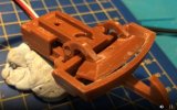
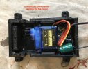
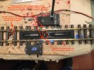
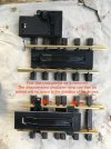
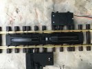
A careful look that the current production 10560 uncoupler proved to be the answer. The uncoupler can be disassembled and the uncoupling ramp moved one tie spacing toward the end of the 10150 track section on which it is mounted. See the first pic below.
There is a molded protrusion on the bottom the the uncoupler ramp that will keep the ramp from lowering completely. Drilling a hole in the double tie solves the problem.
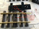
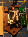
It turns out the existing mounting holes can be used to attach an EPL or similar switch drive to operate the uncoupler in its new position. This drive replaces the uncoupler drive that came with the unit. This was OK with me as only one light post is needed. I actually used a MD Electronics SWD servo switch drive.
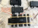
Now comes the only actual modification, read cutting, necessary to make things work. About 3 mm needs to be cut from the frame that surrounds the ramp. This in no way effects the actual operation of the uncoupler. I used a razor saw in a small miter box to trim the ramp frame.
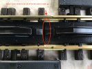
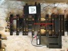
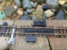
Here's a look of the finished modification. Depending on how you want to wire the uncouplers you can stop here.
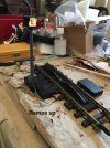
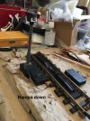
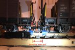
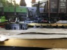
Here's a side view of the uncouplers in action.
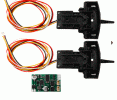
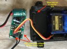
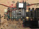
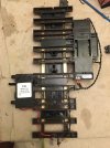
I took a further step to keep the LGB standard 300mm length DCC "drop-in" feature. I drilled some holes in the ties to run the wires feeding the decoders. Eyes on the leads get the DCC signal and power from rail clamps.
I also added a LGB supplementary switch to the unmodified uncoupler. It turns on the light when the ramps are up. The decoders for the two uncouplers have the same DCC switch address. This makes them operate in unison.
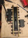
About the only thing I should have done differently is to drill the wire guide holes for the power leads directly under the rails to hide them better. Will do that on my next one.
One nice thing about this mod is that it can be completely reversed. The bit that was actually cut off has no impact on the operation of the uncoupler should one wish to restore it to the out of the box configuration.
Edit added: See post #9 for an update! Total of 8mm trimmed to improve operation.
I felt replacing the manual uncoupler with a second electric unit would solve the issue. The only hinderance is that two out of the box 10560 uncouplers positioned back-to-back don't have the correct ramp spacing to simultaneously lower the coupler hooks on both wagons. I had speculated that I might end up using an old LGB 1055 twin-coil (three wire) uncoupler I had. I would cut it to fit after replacing the drive with a modern two wire EPL or equivalent. This turned out to be a non-starter. The 1055 uncoupler is a completely different design and not amenable to modification.
A careful look that the current production 10560 uncoupler proved to be the answer. The uncoupler can be disassembled and the uncoupling ramp moved one tie spacing toward the end of the 10150 track section on which it is mounted. See the first pic below.

There is a molded protrusion on the bottom the the uncoupler ramp that will keep the ramp from lowering completely. Drilling a hole in the double tie solves the problem.

It turns out the existing mounting holes can be used to attach an EPL or similar switch drive to operate the uncoupler in its new position. This drive replaces the uncoupler drive that came with the unit. This was OK with me as only one light post is needed. I actually used a MD Electronics SWD servo switch drive.

Now comes the only actual modification, read cutting, necessary to make things work. About 3 mm needs to be cut from the frame that surrounds the ramp. This in no way effects the actual operation of the uncoupler. I used a razor saw in a small miter box to trim the ramp frame.

Here's a look of the finished modification. Depending on how you want to wire the uncouplers you can stop here.

Here's a side view of the uncouplers in action.

I took a further step to keep the LGB standard 300mm length DCC "drop-in" feature. I drilled some holes in the ties to run the wires feeding the decoders. Eyes on the leads get the DCC signal and power from rail clamps.

I also added a LGB supplementary switch to the unmodified uncoupler. It turns on the light when the ramps are up. The decoders for the two uncouplers have the same DCC switch address. This makes them operate in unison.

About the only thing I should have done differently is to drill the wire guide holes for the power leads directly under the rails to hide them better. Will do that on my next one.
One nice thing about this mod is that it can be completely reversed. The bit that was actually cut off has no impact on the operation of the uncoupler should one wish to restore it to the out of the box configuration.
Edit added: See post #9 for an update! Total of 8mm trimmed to improve operation.
Last edited:

