Software Tools
Registered
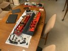
I recently bought a LGB 23450 Green Ge 2/4. The price was very attractive so I expected there may be some issues but 23450s are hard to come by and I was prepared to have do some work on it. It was advertised as having a decoder fitted and running reliably.
It arrived in great physical condition but when put on a DC track would barely move. It took a while to start and would keep moving for a while when power was shut off, so it seemed likely it had a power buffer fitted.
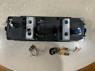
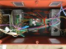
On opening it up, I found this.....
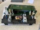
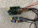
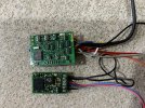
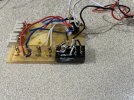
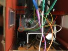
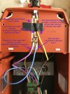
It appears that there is a fairly basic decoder in there with a bunch of stuff added around it. Here's a couple of close ups....
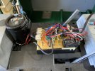
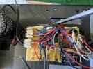
Now, my Massoth DCC kit still isn't installed (due to a bunch of other distractions), so I do not have the wherewithal to "look" at the contents of the decoder, but this whole set up looks so dodgy that I have already ordered a Massoth XLS that I can install myself, with an understanding of exactly what was done.
I'm hoping I can retrieve the decoder from under all the wiring and use it again later, as well as reuse the "stay alive" capacitor with the XLS, but right now I am interested in gaining some understanding of what was done here by the original installer, as well as what they might have been hoping to achieve.
I can see an additional bridge rectifier in there and what looks like a DIP relay but what purpose they serve in unclear. Any ideas?
It arrived in great physical condition but when put on a DC track would barely move. It took a while to start and would keep moving for a while when power was shut off, so it seemed likely it had a power buffer fitted.
On opening it up, I found this.....

It appears that there is a fairly basic decoder in there with a bunch of stuff added around it. Here's a couple of close ups....


Now, my Massoth DCC kit still isn't installed (due to a bunch of other distractions), so I do not have the wherewithal to "look" at the contents of the decoder, but this whole set up looks so dodgy that I have already ordered a Massoth XLS that I can install myself, with an understanding of exactly what was done.
I'm hoping I can retrieve the decoder from under all the wiring and use it again later, as well as reuse the "stay alive" capacitor with the XLS, but right now I am interested in gaining some understanding of what was done here by the original installer, as well as what they might have been hoping to achieve.
I can see an additional bridge rectifier in there and what looks like a DIP relay but what purpose they serve in unclear. Any ideas?
Last edited:

